Model a Compound Gear Train
Planetary gear trains are common in industrial, automotive, and aerospace systems. A typical application is the automatic transmission system of car. From a kinematic point of view, what sets this mechanism apart is the kinematic constraint set between gear pairs. These constraints fix the angular velocity ratios of the gear pairs, causing the gears in each pair to move in sync.
In Simscape™ Multibody™, you represent the kinematic constraint between meshed gears using blocks from the Gears sublibrary. This tutorial shows you how to use these blocks to model a planetary gear train. The gear train contains four bodies:
Sun gear
Planet gear
Ring gear
Planet carrier
Each body, including the planet carrier, can spin about its central axis. In addition, each planet gear can revolve about the sun gear. Joint blocks provide the required degrees of freedom, while gear constraint blocks ensure the gears move as if they were meshed.
Model Sun-Planet Gear Set
Model the gear bodies and connect them with the proper degrees of freedom. In a later step, you add gear constraints to this model.
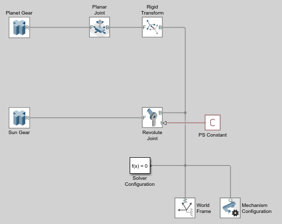
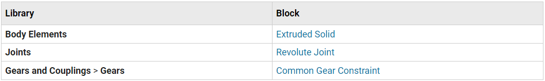
Drag these blocks to a new model.

Connect and name the blocks as shown.
In the Sun Gear block dialog box, specify these parameters.
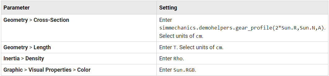
The simmechanics.demohelpers.gear_profile function generates the cross-section matrix for an external gear with an involute tooth profile. The cross-section is approximate. The function is not an official feature; use the function only in this example.
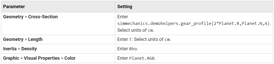
In the Planet Gear block dialog box, specify these parameters.
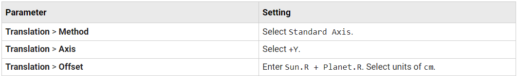
In the Rigid Transform block dialog box, specify these parameters.
In the model workspace, define the block parameters using MATLAB® code:
% Common Parameters
Rho = 2700;
T = 3;
A = 0.8; % Gear Addendum

% Sun Gear Parameters
Sun.RGB = [0.75 0.75 0.75];
Sun.R = 15;
Sun.N = 40;

% Planet Gear Parameters
Planet.RGB = [0.65 0.65 0.65];
Planet.R = 7.5;
Planet.N = Planet.R/Sun.R*Sun.N;
Simulate the model. To induce motion, try adjusting the velocity state targets in the joint block dialog boxes. Notice that the sun and planet gears move independently of each other. To constrain gear motion, you must add a gear constraint block between the gear solid blocks.
To open a copy of the resulting model, at the MATLAB command line, enter:
openExample('sm/DocPlanetaryGearExample','supportingFile','DocPlanetaryGearA.slx')
Constrain Sun-Planet Gear Motion
Specify the kinematic constraints acting between the sun and planet gears. These constraints ensure that the gears move in a meshed fashion.
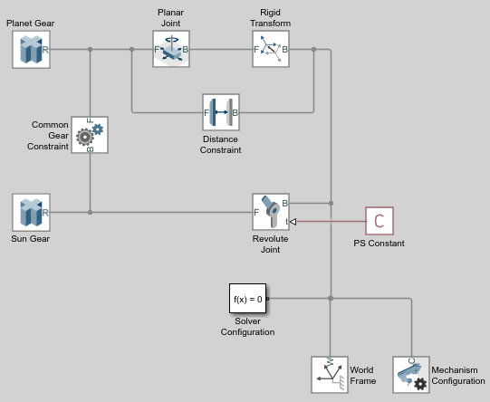
Drag these blocks to the sun-planet gear model.
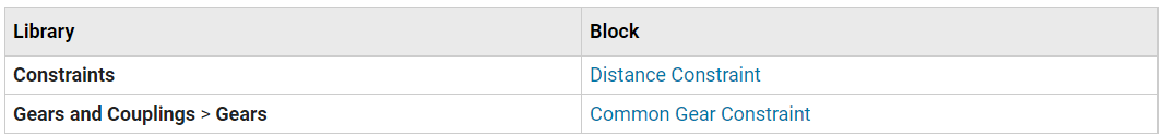
Connect the blocks as shown. The new blocks are highlighted.
In the Common Gear Constraint block dialog box, specify these parameters.
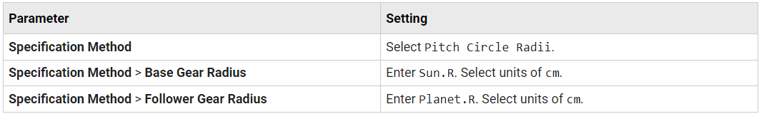
In the Distance Constraint block dialog box, specify this parameter:
Distance — Enter Sun.R + Planet.R. Select units of cm.
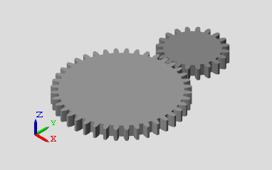
Simulate the model. To induce motion, try adjusting the velocity state targets in the joint block dialog boxes. Notice that the sun and planet gears now move in sync.
To open a copy of the resulting model, at the MATLAB command line, enter:
openExample('sm/DocPlanetaryGearExample','supportingFile','DocPlanetaryGearB.slx')
Add Ring Gear
Model the ring gear body, connect it with the proper degrees of freedom, and constrain its motion with respect to the planet gear.
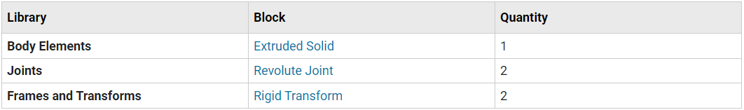
Add these blocks to the sun-planet gear model.
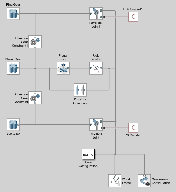
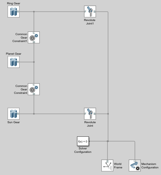
Connect and name the blocks as shown. The new blocks are highlighted.
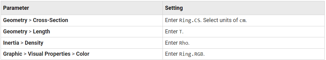
In the Ring Gear block dialog box, specify these parameters.
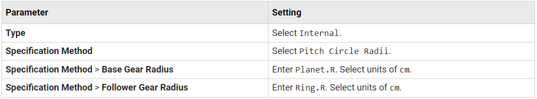
In the Common Gear Constraint1 block dialog box, specify these parameters.
In the model workspace, define the Ring Gear block parameters using MATLAB code:
% Ring Gear Parameters
Ring.RGB = [0.85 0.45 0];
Ring.R = Sun.R + 2*Planet.R;
Ring.N = Ring.R/Planet.R*Planet.N;

Ring.Theta = linspace(-pi/Ring.N,2*pi-pi/Ring.N,100)';
Ring.RO = 1.1*Ring.R;
Ring.CSO = [Ring.RO*cos(Ring.Theta) Ring.RO*sin(Ring.Theta)];
Ring.CSI = simmechanics.demohelpers.gear_profile(2*Ring.R,Ring.N,A);
Ring.CSI = [Ring.CSI; Ring.CSI(1,:)];
Ring.CS = [Ring.CSO; flipud(Ring.CSI)];
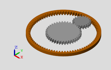
Simulate the model. To induce motion, try adjusting the velocity state targets in the joint block dialog boxes. Notice that the sun, planet, and ring gears move in a meshed fashion.
To open a copy of the resulting model, at the MATLAB command line, enter:
openExample('sm/DocPlanetaryGearExample','supportingFile','DocPlanetaryGearC.slx')
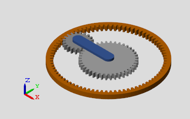
Add Gear Carrier
Up to now, you have kept the sun and planet gears at a fixed distance using a Distance Constraint block. In an actual planetary gear, a gear carrier enforces this constraint. Model the gear carrier and connect it between the sun and planet gears.
Remove these blocks from the planetary gear model:
Planar Joint
Rigid Transform
Distance Constraint
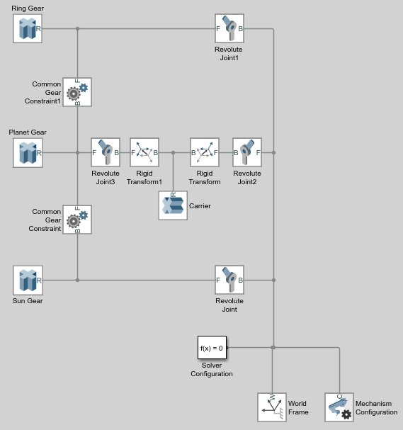
Add these blocks to the planetary gear model.
Connect and name the blocks as shown. Pay close attention to the Rigid Transform block orientation: the B frame ports should face the Solid block. The new blocks are highlighted.
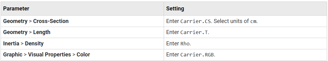
In the Carrier block dialog box, specify these parameters.
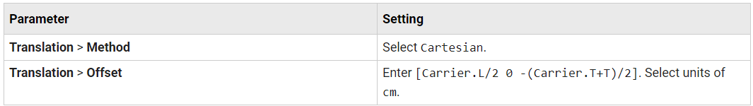
In the Rigid Transform block dialog box, specify these parameters.
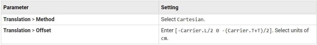
In the Rigid Transform1 block dialog box, specify these parameters.
In the model workspace, define the Carrier block parameters using MATLAB code:
% Gear Carrier Parameters
Carrier.RGB = [0.25 0.4 0.7];
Carrier.L = Sun.R + Planet.R;
Carrier.W = 2*T;
Carrier.T = T/2;

Theta = (90:1:270)'*pi/180;
Beta = (-90:1:90)'*pi/180;

Carrier.CS = [-Carrier.L/2 + Carrier.W/2*cos(Theta) ...
Carrier.W/2*sin(Theta); Carrier.L/2 + Carrier.W/2*cos(Beta), ...
Carrier.W/2*sin(Beta)];
Simulate the model. To induce motion, try adjusting the velocity state targets in the joint block dialog boxes. Notice that the gear carrier now performs the task of the Distance Constraint block.
To open a copy of the resulting model, at the MATLAB command line, enter:
openExample('sm/DocPlanetaryGearExample','supportingFile','DocPlanetaryGearD.slx')
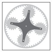
Add More Planet Gears
Experiment with the model by adding more planet gears. Remember that you must change the Carrier body to accommodate any additional planet gears.
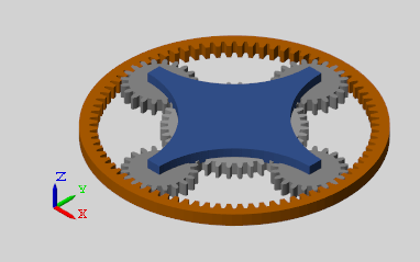
To see a model with four planet gears, at the MATLAB command line, enter:
openExample('sm/DocPlanetaryGearExample','supportingFile','DocPlanetaryGearE.slx')