Main Content

Synchronous Machine pu Standard

Model dynamics of three-phase round-rotor or salient-pole synchronous machine using standard parameters in pu units

  • Synchronous Machine pu Standard block

Libraries:
Simscape / Electrical / Specialized Power Systems / Electrical Machines

Description

The Synchronous Machine pu Standard block models a synchronous machine in generator or motor mode using standard parameters in pu units. The operating mode is dictated by the sign of the mechanical power (positive for generator mode or negative for motor mode). The electrical part of the machine is represented by a sixth-order state-space model and the mechanical part is the same as in the Simplified Synchronous Machine block.

For more information on the pu units system, see Per-Unit System of Units.

The model takes into account the dynamics of the stator, field, and damper windings. The equivalent circuit of the model is represented in the rotor reference frame (qd frame). Stator windings are connected in wye to an internal neutral point. All rotor parameters and electrical quantities are viewed from the stator and identified by primed variables. The subscripts are:

  • d,qd- and q-axis quantity

  • R,s — Rotor and stator quantity

  • l,m — Leakage and magnetizing inductance

  • f,k — Field and damper winding quantity

The electrical model of the machine is shown in these diagrams.

Dynamic Model with Unequal Mutual Inductance

The conventional theory of synchronous machine modeling for stability analysis assumes that the mutual inductances between the armature, damper, and field on direct-axis windings are identical. Generally, damper windings are near the air gap, and as a result the flux linking damper circuits are almost equal to the flux linking armature. This hypothesis produces acceptable outcomes for a wide range of stability studies, especially those on the side of the network. However, when it comes to field current studies, there is considerable error. The equivalent circuit dynamic model of a synchronous machine may include an additional inductance representing the difference between field-damper and field-armature mutual inductances on the D-axis [1]. This inductance is typically called Canay inductance. Canay inductance corresponds to the leakage flux, ΦC, in the following figure and is interpreted as a corrective element in an equivalent model that may have a negative value [2].
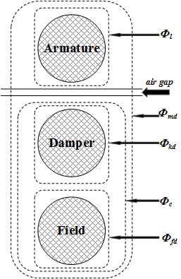
The IEEE® standard 1110-2002 [3] presents the direct and quadratic axes of the synchronous machine dynamic model as shown in the diagrams.

The relevant equations are:

Vd=idRsωψq+dψddtVq=iqRs+ωψd+dψqdtV0=i0R0+dψ0dtVfd=dψfddt+Rfdifd0=dψkddt+Rkdikd0=dψkq1dt+Rkq1ikq10=dψkq2dt+Rkq2ikq2[ψdψkdψfd]=[L+mdLlLmdLmdLmdLlkd+ Lf1d+ LmdLf1d+ LmdLmdLf1d+ LmdLlfd+ Lf1d+ Lmd][idikdifd][ψqψkq1ψkq2]=[Lmq+LlLmqLmqLmqLmq+Lkq1LmqLmqLmqLmq+Lkq2][iqikq1ikq2]

Examples

expand all

The Subsyncronous Resonance in Steam Turbine and Governor System example uses the Synchronous Machine pu Standard block to model sub-synchronous resonance (SSR) in a steam turbine and governor on a series-compensated network.

Assumptions and Limitations

In discrete systems, when you set the Discrete solver model parameter of a Synchronous Machine block to Trapezoidal non iterative, you might have to connect a small parasitic resistive load at the machine terminals to avoid numerical oscillations. Large sample times require larger loads. The minimum resistive load is proportional to the sample time. As a rule of thumb, remember that with a 25 μs time step on a 60 Hz system, the minimum load is approximately 2.5% of the machine nominal power. For example, a 200 MVA synchronous machine in a power system discretized with a 50 μs sample time requires approximately 5% of resistive load or 10 MW. If the sample time is reduced to 20 μs, a resistive load of 4 MW should be sufficient.

However, if you set the Discrete solver model parameter of a Synchronous Machine block to Trapezoidal iterative (alg. loop), you can use a negligible parasitic load (below 0.1% of nominal power) while preserving numerical stability. This iterative model produces an algebraic loop and results in slower simulation speed.

Ports

Input

expand all

Mechanical power at the machine's shaft, in pu. In generator mode, this input can be a positive constant or function or the output of a prime mover block (see the Hydraulic Turbine and Governor or Steam Turbine and Governor blocks). In motor mode, this input is usually a negative constant or function.

Dependencies

To enable this port, set the Mechanical input parameter (Configuration tab) to Mechanical power Pm.

Machine speed, in rad/s.

Dependencies

To enable this port, set the Mechanical input parameter (Configuration tab) to Speed w.

Field voltage, in pu. This voltage can be supplied by a voltage regulator in generator mode (see the Excitation System block). In motor mode, this value of this input is usually a constant.

Output

expand all

Measurement signals, returned as a 24-element vector. You can demultiplex these signals by using the Bus Selector block.

Name

Definition

Units

ias

Stator current is_a

pu

ibs

Stator current is_b

pu

ics

Stator current is_c

pu

iq

Stator current iq

pu

id

Stator current id

pu

ifd

Field current ifd

pu

ikq1

Damper winding current ikq1

pu

Ikq2

Damper winding current ikq2

pu

ikd

Damper winding current ikd

pu

phimq

Mutual flux phimq

pu

phimd

Mutual flux phimd

pu

vq

Stator voltage vq

pu

vd

Stator voltage vd

pu

lmq

Lmq saturated inductance

pu

lmd

Lmd saturated inductance

pu

dtheta

Rotor angle deviation d_theta

rad

w

Rotor speed wm

pu

Pe

Electrical power Pe

pu

dw

Rotor speed deviation dw

pu

theta

Rotor mechanical angle theta

degree

Te

Electromagnetic torque Te

pu

delta

Load angle delta

degree

Pe0

Output active power Peo

pu

Qe0

Output reactive power Qeo

pu

The angular deviation of the rotor angle theta represents the electrical angle giving the instantaneous position of the rotor with respect to a common reference rotating at synchronous speed. This angle is useful in stability studies to measure the relative positions of the rotors of different machines in a network. The positions of the rotors are then measured with respect to the theta position of a given machine chosen as a reference.

Conserving

expand all

Specialized electrical conserving port associated with the phase A electrical terminal.

Specialized electrical conserving port associated with the phase B electrical terminal.

Specialized electrical conserving port associated with the phase C electrical terminal.

Mechanical rotational conserving port associated with the machine rotor shaft.

Dependencies

To enable this port, set the Mechanical input parameter (Configuration tab) to Mechanical rotational port.

Parameters

expand all

Specify standard parameters, also known as operational parameters, of the synchronous machine (such as steady-state, transient, and/or subtransient reactances and time constants) as inputs to the block. Typically, machine manufacturers provide operational parameters.

In power system analysis software, the synchronous machine equations are commonly solved using the direct-quadrature-zero transformation technique. A data translation technique calculates fundamental parameters from standard parameters [2], [3].

Configuration

Set of predetermined electrical and mechanical parameters for various synchronous machine ratings of power (kVA), phase-to-phase voltage (V), frequency (Hz), and rated speed (rpm).

Select one of the preset models to load the corresponding electrical and mechanical parameters. Choices are:

  • 01: 50Hz 400V 8.1kVA 1500RPM

  • 02: 50Hz 400V 16kVA 1500RPM

  • 03: 50Hz 400V 31.3kVA 1500RPM

  • 04: 50Hz 400V 42.5kVA 1500RPM

  • 05: 50Hz 400V 60kVA 1500RPM

  • 06: 50Hz 400V 85kVA 1500RPM

  • 07: 50Hz 400V 250kVA 1500RPM

  • 08: 50Hz 400V 325kVA 1500RPM

  • 09: 50Hz 400V 670kVA 1500RPM

  • 10: 50Hz 400V 910kVA 1500RPM

  • 11: 50Hz 400V 1320kVA 1500RPM

  • 12: 50Hz 400V 2000kVA 1500RPM

  • 13: 60Hz 460V 10.2kVA 1800RPM

  • 14: 60Hz 460V 20kVA 1800RPM

  • 15: 60Hz 460V 37.5kVA 1800RPM

  • 16: 60Hz 460V 52.5kVA 1800RPM

  • 17: 60Hz 460V 72.5kVA 1800RPM

  • 18: 60Hz 460V 100kVA 1800RPM

  • 19: 60Hz 460V 300kVA 1800RPM

  • 20: 60Hz 460V 406kVA 1800RPM

  • 21: 60Hz 460V 800kVA 1800RPM

  • 22: 60Hz 460V 1075kVA 1800RPM

  • 23: 60Hz 460V 1588kVA 1800RPM

  • 24: 60Hz 460V 2500kVA 1800RPM

Select No (default) if you do not want to use a preset model or if you want to modify some of the parameters of a preset model, as described below.

When you select a preset model, the electrical and mechanical parameters in the Parameters tab are dimmed. To start from a preset model and then modify the machine parameters:

  1. Select the preset model you want to initialize the parameters.

  2. Change the Preset model parameter to No. This action does not change the machine parameters, but breaks the connection with the preset model.

  3. Modify the machine parameters as you want.

Whether to represent the mechanical power applied to the shaft or the rotor speed as a Simulink® input of the block, or to represent the machine shaft with a Simscape™ rotational mechanical port.

Select Mechanical power Pm to specify a mechanical power input, in pu, and expose the Pm port. The machine speed is determined by the inertia constant H and by the difference between the mechanical torque Tm, which results from the applied mechanical power Pm, and the internal electromagnetic torque Te. When the speed is positive, a positive mechanical power signal indicates generator mode and a negative signal indicates motor mode.

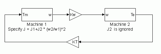
Select Speed w to specify a speed input in pu and expose the w port. The machine speed is imposed and the mechanical part of the model (the inertia constant H) is ignored. Using the speed as the mechanical input allows you to model a mechanical coupling between two machines.

The next figure indicates how to model a stiff shaft interconnection in a motor-generator set where both machines are synchronous machines.

The speed output of machine 1 (the motor) is connected to the speed input of machine 2 (the generator). In this figure, friction torque is ignored in machine 2. Therefore, its electromagnetic torque output Te corresponds to the mechanical torque Tm applied to the shaft of machine 1. The corresponding mechanical input power of machine 1 is computed as Pm = Tm*w. The Kw factor takes into account the speed units of both machines (pu) and the gear box ratio w2/w1. The KT factor takes into account the torque units of both machines (pu) and the machine ratings. Also, because inertia J2 is ignored in machine 2, J2 refers to the speed of machine 1 and must be added to machine 1 inertia, J1.

Select Mechanical rotational port to expose a Simscape mechanical rotational port, S, that allows you to connect of the machine shaft to another machine shaft or to other Simscape blocks that have mechanical rotational ports.

The figure indicates how to connect an Ideal Torque Source block from the Simscape library to the machine shaft port to represent the machine in motor mode or generator mode when the rotor speed is positive.

Specify the rotor type as either Salient-pole or Round (cylindrical). The setting affects the number of rotor circuits in the q-axis (damper windings).

When this check box is selected, the measurement output uses the signal names to identify the bus labels. Select this option for applications that require bus signal labels to have only alphanumeric characters.

When this check box is cleared, the measurement output uses the signal definition to identify the bus labels. The labels contain nonalphanumeric characters that are incompatible with some Simulink applications.

Parameters

Total three-phase apparent power (VA), RMS line-to-line voltage (pu), frequency (Hz), and field current (pu).

This parameter is identical to the Nominal power, voltage, frequency, field current [ Pn(VA) Vn(Vrms) fn(Hz) ifn(A) ] parameter of the Synchronous Machine SI Fundamental block, except that you do not specify a nominal field current. This value is not required because the Synchronous Machine pu Standard block does not need the transformation ratio. Because rotor quantities are viewed from the stator, they are converted to pu using the stator base quantities derived from the preceding three nominal parameters.

d-axis synchronous reactance Xd, transient reactance Xd', and subtransient reactance Xd''; the q-axis synchronous reactance Xq and subtransient reactance Xq''; and the leakage reactance Xl (all in pu).

Dependencies

To enable this parameter, set Rotor type to Salient-pole.

d-axis synchronous reactance Xd, transient reactance Xd', and subtransient reactance Xd''; the q-axis synchronous reactance Xq, transient reactance Xq', and subtransient reactance Xq''; and the leakage reactance Xl (all in pu).

Dependencies

To enable this parameter, set Rotor type to Round.

Time constant for the d axis.

Time constant for the q axis.

Time constants, all in s, for the following:

  • d-axis transient open-circuit (Tdo')

  • d-axis subtransient open-circuit (Tdo'')

  • q-axis subtransient open-circuit (Tqo'')

Dependencies

To enable this parameter, set Rotor type to Salient-pole, d axis to Open-circuit, and q axis to Open-circuit.

Time constants, all in s, for the following:

  • d-axis transient open-circuit (Tdo')

  • d-axis subtransient open-circuit (Tdo'')

  • q-axis transient open-circuit (Tqo')

  • q-axis subtransient open-circuit (Tqo'')

Dependencies

To enable this parameter, set Rotor type to Round, d axis to Open-circuit, and q axis to Open-circuit.

Time constants, all in s, for the following:

  • d-axis transient open-circuit (Tdo')

  • d-axis subtransient open-circuit (Tdo'')

  • q-axis subtransient short-circuit (Tq'')

Dependencies

To enable this parameter, set Rotor type to Salient-pole, d axis to Open-circuit, and q axis to Short-circuit.

Time constants, all in s, for the following:

  • d-axis transient open-circuit (Tdo')

  • d-axis subtransient open-circuit (Tdo'')

  • q-axis transient short-circuit (Tq')

  • q-axis subtransient short-circuit (Tq'')

Dependencies

To enable this parameter, set Rotor type to Round, d axis to Open-circuit, and q axis to Short-circuit.

Time constants, all in s, for the following:

  • d-axis transient short-circuit (Td')

  • d-axis subtransient short-circuit (Td'')

  • q-axis subtransient open-circuit (Tqo'')

Dependencies

To enable this parameter, set Rotor type to Salient-pole, d axis to Short-circuit, and q axis to Open-circuit.

Time constants, all in s, for the following:

  • d-axis transient short-circuit (Td')

  • d-axis subtransient short-circuit (Td'')

  • q-axis transient open-circuit (Tqo')

  • q-axis subtransient open-circuit (Tqo'')

Dependencies

To enable this parameter, set Rotor type to Round, d axis to Short-circuit, and q axis to Open-circuit.

Time constants, all in s, for the following:

  • d-axis transient short-circuit (Td')

  • d-axis subtransient short-circuit (Td'')

  • q-axis subtransient short-circuit (Tq'')

Dependencies

To enable this parameter, set Rotor type to Salient-pole, d axis to Short-circuit, and q axis to Short-circuit.

Time constants, all in s, for the following:

  • d-axis transient short-circuit (Td')

  • d-axis subtransient short-circuit (Td'')

  • q-axis transient short-circuit (Tq')

  • q-axis subtransient short-circuit (Tq'')

Dependencies

To enable this parameter, set Rotor type to Round, d axis to Short-circuit, and q axis to Short-circuit.

Stator resistance Rs, in pu.

Inertia constant H (s), which is the ratio of energy stored in the rotor at nominal speed over the nominal power of the machine, friction factor F (pu torque/pu speed), and the number of pole pairs p. Friction torque Tf is proportional to rotor speed ω (Tf = F.ω, where all quantities are expressed in pu).

Dependencies

To enable this parameter, set Mechanical input to Mechanical power Pm or Mechanical rotational port.

Number of pole pairs of the synchronous machine.

Dependencies

To enable this parameter, set Mechanical input to Speed w.

Initial speed deviation Δω (percent of nominal speed), electrical angle of the rotor Θe (degrees), line current magnitudes ia, ib, ic (pu) and phase angles pha, phb, phc (degrees), and the initial field voltage Vf (pu). You can compute these values automatically by using the Load Flow tool or the Machine Initialization tool of the powergui block.

Whether the magnetic saturation of the rotor and stator iron is simulated.

Select this check box to provide the matrix of parameters for simulating the saturation.

Clear this check box to not model saturation in your simulation. In this case, the relationship between the ifd and Vt is linear (no saturation).

No-load saturation curve parameters. The magnetic saturation of the stator and rotor iron is modeled by a piecewise linear relationship specifying points on the no-load saturation curve. The first row of this matrix contains the values of field currents (in pu). The second row contains values of corresponding terminal voltages (in pu). The first point (first column of the matrix) must be different from [0,0]. This point corresponds to the point where the effect of saturation begins. For saturation, the nominal field current and nominal RMS line-to-line voltage are the base values for the field current and terminal voltage, respectively.

Click Plot to view the no-load saturation curve.

Dependencies

To enable this parameter, select Simulate saturation.

Advanced

To enable the Advanced tab, in the powergui block, set Simulation type to Discrete and clear Automatically handle discrete solver.

Sample time used by the block. To inherit the sample time specified in the powergui block, set this parameter to −1.

Integration method used by the block when the Solver type parameter of the powergui block is set to Discrete.

The Discrete solver model is automatically set to Trapezoidal robust when you select the Automatically handle Discrete solver and Advanced tab solver settings of blocks parameter of the powergui block.

The Trapezoidal non iterative and Trapezoidal iterative (alg. loop) methods are no longer recommended for discretizing the Synchronous Machine pu Standard block. Trapezoidal non iterative requires you to add non-negligible shunt loads at the machine terminals to guarantee simulation stability, and Trapezoidal iterative (alg. loop) may fail to converge and cause the simulation to stop when the number of machines increases in the model.

The Trapezoidal robust and Backward Euler robust methods allow you to eliminate the need to use parasitic loads and simulate a machine without loads. To eliminate topological errors of machines connected to an inductive circuit (for example, a circuit breaker connected in series with the machine); the machine models a negligible internal load of 0.01% of nominal power.

The Trapezoidal robust method is slightly more accurate than the Backward Euler robust method, especially when the model is simulated at larger sample times. The Trapezoidal robust method may produce slight damped numerical oscillations on machine voltage at no-load conditions, while the Backward Euler robust method prevents oscillations and maintains good accuracy.

For more information on what method to use in your application, see Simulating Discretized Electrical Systems.

Load Flow

The load flow parameters are used to define block parameters for use with the Load Flow tool of the powergui block. These load flow parameters are used for model initialization only. They have no impact on the block model or on the simulation performance.

Generator type of the machine. Choice are:

  • swing — Implements a generator controlling magnitude and phase angle of its terminal voltage. The reference voltage magnitude and angle are specified by the Swing bus or PV bus voltage and Swing bus voltage angle parameters of the Load Flow Bus block connected to the machine terminals.

  • PV — Implements a generator controlling its output active power P and voltage magnitude V. P is specified by the Active power generation P (W) parameter of the block. V is specified by the Swing bus or PV bus voltage parameter of the Load Flow Bus block connected to the machine terminals. You can control the minimum and maximum reactive power generated by the block by using the Minimum reactive power Qmin (var) and Maximum reactive power Qmax (var) parameters.

  • PQ — Implements a generator controlling its output active power P and reactive power Q. P and Q are specified by the Active power generation P (W) and Reactive power generation Q (var) parameters of the block, respectively.

Active power that you want generated by the machine, in watts. When the machine operates in motor mode, you specify a negative value.

Dependencies

To enable this parameter, set Generator type to PV or PQ.

Reactive power that you want generated by the machine, in vars. A negative value indicates that the reactive power is absorbed by the machine.

Dependencies

To enable this parameter, set Generator type to PQ.

Minimum reactive power that can be generated by the machine while keeping the terminal voltage at its reference value. This reference voltage is specified by the Swing bus or PV bus voltage parameter of the Load Flow Bus block connected to the machine terminals. The default value is -inf, which means that there is no lower limit on the reactive power output.

Dependencies

To enable this parameter, set Generator type to PV.

Maximum reactive power that can be generated by the machine while keeping the terminal voltage at its reference value. This reference voltage is specified by the Swing bus or PV bus voltage parameter of the Load Flow Bus block connected to the machine terminals. The default value is inf, which means that there is no upper limit on the reactive power output.

Dependencies

To enable this parameter, set Generator type to PV.

References

[1] Canay, I.M. "Causes of Discrepancies on Calculation of Rotor Quantities and Exact Equivalent Diagrams of the Synchronous Machine." IEEE Transactions on Power Apparatus and Systems. PAS-88, no. 7 (1969): 1114–1120.

[2] Moeini, A., et al. “Synchronous Machine Stability model, an Update to IEEE Std 1110-2002 Data Translation Technique.” IEEE standards panel sessions. 2018.

[3] IEEE Guide for Synchronous Generator Modeling Practices and Applications in Power System Stability Analyses. IEEE Std 1110-2002 (Revision of IEEE Std 1110-1991 [2003]): 1–72.

[4] Krause, P.C. Analysis of Electric Machinery. Section 12.5. New York: McGraw-Hill, 1986.

[5] Kundur, P. Power System Stability and Control. New York, McGraw-Hill, 1994.

Extended Capabilities

C/C++ Code Generation
Generate C and C++ code using Simulink® Coder™.

Version History

Introduced before R2006a
Go to top of page