Wind Farm Using Doubly-Fed Induction Generators
Description of the Wind Farm
The example described in this section illustrates application of Simscape™ Electrical™ Specialized Power Systems software to study the steady-state and dynamic performance of a 9 MW wind farm connected to a distribution system.
The wind farm consists of six 1.5 MW wind turbines connected to a 25 kV distribution system exporting power to a 120 kV grid through a 30 km 25 kV feeder. A 2300V, 2 MVA plant consisting of a motor load (1.68 MW induction motor at 0.93 PF) and of a 200 kW resistive load is connected on the same feeder at bus B25. A 500 kW load is also connected on the 575 V bus of the wind farm. The single-line diagram of this system is illustrated in Single-Line Diagram of the Wind Farm Connected to a Distribution System.
Single-Line Diagram of the Wind Farm Connected to a Distribution System
![]()
Both the wind turbine and the motor load have a protection system monitoring voltage, current and machine speed. The DC link voltage of the DFIG is also monitored. Wind turbines use a doubly-fed induction generator (DFIG) consisting of a wound rotor induction generator and an AC/DC/AC IGBT-based PWM converter. The stator winding is connected directly to the 60 Hz grid while the rotor is fed at variable frequency through the AC/DC/AC converter. The DFIG technology allows extracting maximum energy from the wind for low wind speeds by optimizing the turbine speed, while minimizing mechanical stresses on the turbine during gusts of wind. The optimum turbine speed producing maximum mechanical energy for a given wind speed is proportional to the wind speed. Another advantage of the DFIG technology is the ability for power electronic converters to generate or Turbine Power Characteristics absorb reactive power, thus eliminating the need for installing capacitor banks as in the case of squirrel-cage induction generators.
This system is available in the Wind Farm - Doubly-Fed Induction Generator (DFIG) Phasor Model model. Load this model and save it
in your working directory as case3to allow further modifications
to the original system. In this case study, the rotor is running at subsynchronous
speed for wind speeds lower than 10 m/s and it is running at a super-synchronous
speed for higher wind speeds. The turbine mechanical power as function of turbine
speed is displayed in for wind speeds ranging from 5 m/s to 16.2 m/s. These
characteristics are obtained with the specified parameters of the Turbine
data (Turbine Power Characteristics).
Turbine Power Characteristics
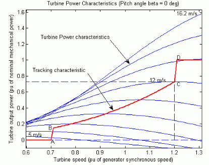
The DFIG is controlled to follow the ABCD curve in Turbine Power Characteristics. Turbine speed optimization is obtained between point B and point C on this curve.
The wind turbine model is a phasor model that allows transient stability type studies with long simulation times. In this case study, the system is observed during 50 s. The 6-wind-turbine farm is simulated by a single wind-turbine block by multiplying the following three parameters by six, as follows:
The nominal wind turbine mechanical output power: 6*1.5e6 watts, specified in the
Turbine datamenuThe generator rated power: 6*1.5/0.9 MVA (6*1.5 MW at 0.9 PF), specified in the
Generator datamenuThe nominal DC bus capacitor: 6*10000 microfarads, specified in the
Converters datamenu
The mode of operation is set to Voltage regulation in the
Control Parameters dialog box. The terminal
voltage will be controlled to a value imposed by the reference voltage (Vref=1 pu)
and the voltage droop (Xs=0.02 pu).
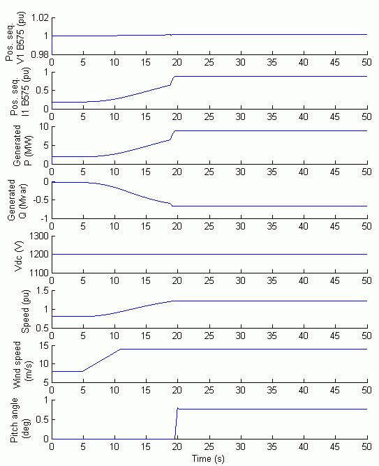
Turbine Response to a Change in Wind Speed
Observe the turbine response to a change in wind speed. Initially, wind speed is
set at 8 m/s, and then at t=5s, wind speed increases suddenly at 14 m/s. Waveforms for a Gust of Wind (Wind Farm in Voltage Regulation Mode)
illustrates the waveforms associated with this simulation. At t=5 s, the generated
active power starts increasing smoothly (together with the turbine speed) to reach
its rated value of 9MW in approximately 15s. Over that time frame the turbine speed
increases from 0.8 pu to 1.21 pu. Initially, the pitch angle of the turbine blades
is zero degree and the turbine operating point follows the red curve of the turbine
power characteristics up to point D. Then the pitch angle is increased from 0 deg to
0.76 deg to limit the mechanical power. Observe also the voltage and the generated
reactive power. The reactive power is controlled to maintain a 1 pu voltage. At
nominal power, the wind turbine absorbs 0.68 Mvar (generated Q=-0.68 Mvar) to
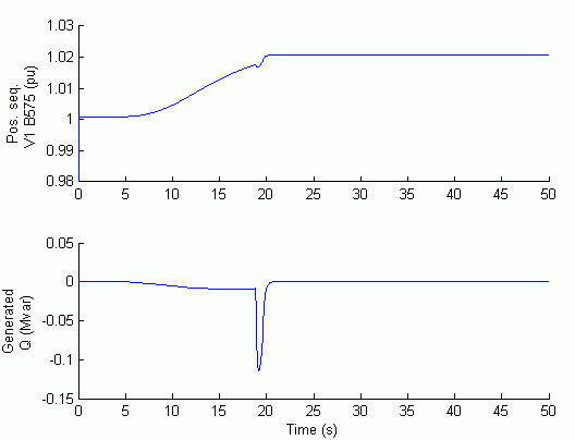
control voltage at 1pu. If you change the mode of operation to Var
regulation with the Generated reactive power
Qref set to zero, you will observe that the voltage increases to
1.021 pu when the wind turbine generates its nominal power at unity power factor
(Waveforms for a Gust of Wind (Wind Farm in Var Regulation Mode)).
Waveforms for a Gust of Wind (Wind Farm in Voltage Regulation Mode)
Waveforms for a Gust of Wind (Wind Farm in Var Regulation Mode)
Simulation of a Voltage Sag on the 120 kV System
Now observe the impact of a voltage sag resulting from a remote fault on the 120
kV system. In this simulation the mode of operation is initially Var
regulation with Qref=0 and the wind speed is constant at 8 m/s. A 0.15
pu voltage drop lasting 0.5 s is programmed, in the 120 kV voltage source menu, to
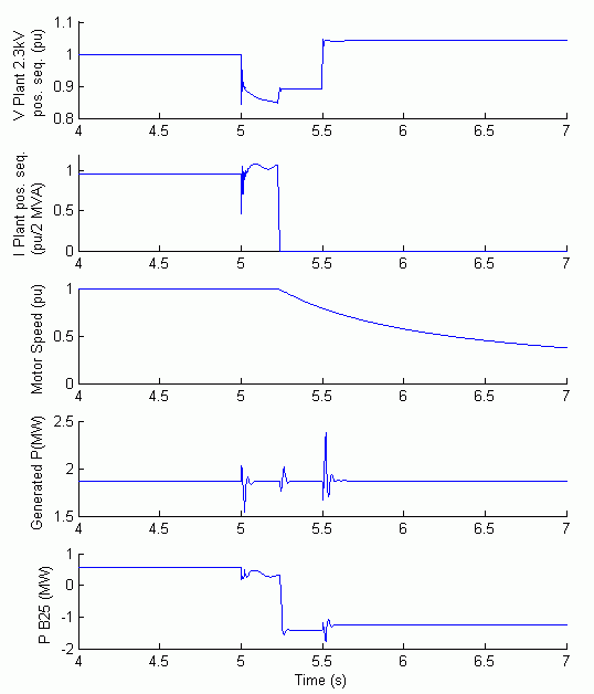
occur at t=5 s. The simulation results are illustrated in Voltage Sag on the 120 kV System (Wind Farm in Var Regulation Mode).
Observe the plant voltage and current as well as the motor speed. Note that the wind
farm produces 1.87 MW. At t=5 s, the voltage falls below 0.9 pu and at t=5.22 s, the
protection system trips the plant because an undervoltage lasting more than 0.2 s
has been detected (exceeding protection settings for the Plant subsystem). The plant
current falls to zero and motor speed decreases gradually, while the wind farm
continues generating at a power level of 1.87 MW. After the plant has tripped, 1.25
MW of power (P_B25 measured at bus B25) is exported to the grid.
Voltage Sag on the 120 kV System (Wind Farm in Var Regulation Mode)
Now, the wind turbine control mode is changed to Voltage
regulation and the simulation is repeated. You will notice that the
plant does not trip anymore. This is because the voltage support provided by the 5
Mvar reactive power generated by the wind turbines during the voltage sag keeps the
plant voltage above the 0.9 pu protection threshold. The plant voltage during the
voltage sag is now 0.93 pu (Voltage Sag on the 120 kV System (Wind Farm in Voltage Regulation Mode)).
Voltage Sag on the 120 kV System (Wind Farm in Voltage Regulation Mode)
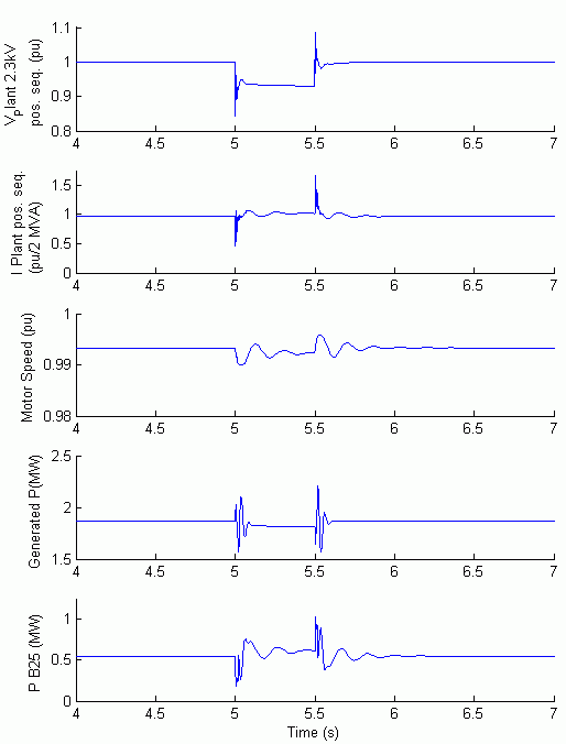
Simulation of a Fault on the 25 kV System
Finally, now observe the impact of a single phase-to-ground fault occurring on the
25 kV line. At t=5 s a 9 cycle (0.15 s) phase-to-ground fault is applied on phase A
at B25 bus. When the wind turbine is in Voltage regulation mode,
the positive sequence voltage at wind turbine terminals (V1_B575) drops to 0.8 pu
during the fault, which is above the undervoltage protection threshold (0.75 pu for
a t>0.1 s). The wind farm therefore stays in service (Wind Farm Waveforms During Fault at Bus B25 (Wind Farm in Voltage Regulation Mode)). However, if the Var regulation mode is used with Qref=0, the
voltage drops under 0.7 pu and the undervoltage protection trips the wind farm. We
can now observe that the turbine speed increases. At t=40 s the pitch angle starts
to increase to limit the speed (Wind Farm Waveforms During Fault at Bus B25 (Wind Farm in Var Regulation Mode)).
Wind Farm Waveforms During Fault at Bus B25 (Wind Farm in Voltage Regulation Mode)

Wind Farm Waveforms During Fault at Bus B25 (Wind Farm in Var Regulation Mode)

Select a Web Site
Choose a web site to get translated content where available and see local events and offers. Based on your location, we recommend that you select: United States.
You can also select a web site from the following list
Americas
- América Latina (Español)
- Canada (English)
- United States (English)
Europe
- Belgium (English)
- Denmark (English)
- Deutschland (Deutsch)
- España (Español)
- Finland (English)
- France (Français)
- Ireland (English)
- Italia (Italiano)
- Luxembourg (English)
- Netherlands (English)
- Norway (English)
- Österreich (Deutsch)
- Portugal (English)
- Sweden (English)
- Switzerland
- United Kingdom (English)
Asia Pacific
- Australia (English)
- India (English)
- New Zealand (English)
- 中国
- 日本Japanese (日本語)
- 한국Korean (한국어)