SM Field-Oriented Control
Synchronous machine field-oriented control
Libraries:
Simscape /
Electrical /
Control /
SM Control
Description
The SM Field-Oriented Control block implements a synchronous machine (SM) field-oriented control structure. Field Oriented Control (FOC) is a performant AC motor control strategy that decouples torque and flux by transforming the stationary phase currents to a rotating frame. Use FOC when rotor speed and position are known and your application requires:
High torque and low current at startup
High efficiency
Equations
The SM FOC is made up of several control blocks from the Control library. To see and modify these blocks and the FOC's internal structure, right-click the block in Simulink and select View Mask > Look Inside Mask. The overall control structure is made up of several parts:
The outer loop controller converts the reference signal you supply to the reference d-axis, q-axis, and field currents.
You can choose the type of reference signal you provide using the
Control modeparameter:Velocity control— Control or regulate the rotation speed of the synchronous machine. An internal Velocity Controller block generates a reference torque from the rotor speed error.Torque control— Control or regulate the mechanical torque of the SM.
An internal SM Current Reference Generator block generates the reference currents using a proportional-integral (PI) controller, minimizing the torque error.
The inner loop controller converts the current references into voltage references. An internal SM Current Controller generates the voltage references using a PI controller minimizing the current error, and the feedforward terms:
where:
ωe is the rotor electrical angular velocity.
Ld and Lq are the d- and q-axis stator inductances.
Lmf is the mutual field armature inductance.
id, iq, and if, are the stator d-q and field excitation currents, respectively.
The PWM Generator converts the reference stator voltages into gate pulses to be passed to a Power Converter that is powering the stator windings of the synchronous machine.
The Excitation PWM Generator converts the reference field voltage into gate pulses to be passed to a DC-DC Chopper powering the SM field winding.
This diagram shows the overall architecture of the block.
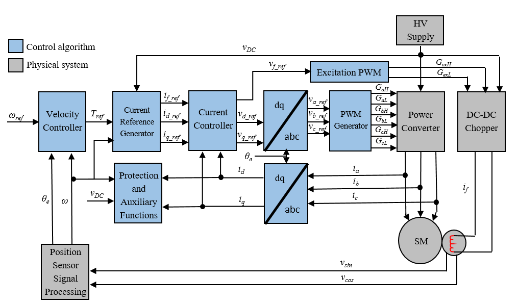
In the diagram:
ω and ωref are the measured and reference angular velocities, respectively.
Tref is the reference electromagnetic torque. If you configure the block for speed control, a Velocity Controller generates this reference torque.
i and v are stator currents and voltages. Subscripts d, q, and f, represent the d-axis, q-axis, and field winding. Subscripts a, b, and c, represent the three stator windings.
θe is the rotor electrical angle.
G is a gate pulse, subscripts H and L represent high and low, and subscripts a, b, and c, represent the three stator windings. Subscript ex represents the field excitation pulses.
You can choose to implement either velocity or torque control with
the Control mode parameter. The block implements velocity
control exactly as shown in the diagram. The block implements torque control by
removing the Velocity Controller block and accepting the reference torque
directly.
Assumptions
The machine parameters are known.
Limitations
The control structure is implemented with a single sample rate.
Examples
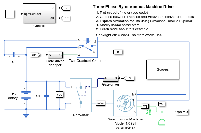
Three-Phase Synchronous Machine Drive
Control the rotor speed in a Synchronous Machine (SM) based electrical drive. A high-voltage battery feeds the SM through a controlled three-phase converter for the stator windings and through a controlled two-quadrant chopper for the rotor winding. Use the model to design the SM controller, selecting architecture and gains to achieve desired performance. The Scopes subsystem contains scopes that allow you to see the simulation results.
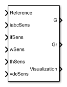
Ports
Input
Output
Parameters
References
[1] Märgner, M., and W. Hackmann. "Control challenges of an externally excited synchronous machine in an automotive traction drive application." In Emobility - Electrical Power Train. (2010): 1–6. 10.1109/EMOBILITY.2010.5668056.
[2] Carpiuc, S., C. Lazar, and D. Patrascu. "Optimal Torque Control of the Externally Excited Synchronous Machine." Journal of Control Engineering and Applied Informatics. 14, no 2 (2012): 80–88.
Extended Capabilities
Version History
Introduced in R2018a