Wye-Connected Variable Load (lagging)
Three-phase variable, lagging load wired in wye configuration
Libraries:
Simscape /
Electrical /
Passive /
RLC Assemblies
Description
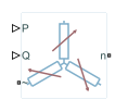
The Wye-Connected Variable Load (lagging) block models a three-phase variable, lagging load wired in a wye configuration. Each limb of the load contains a resistor (R) and an inductor (L) connected in series. The block calculates the resistance and inductance required to draw the real and reactive powers of the physical signal inputs P and Q at the rated voltage and rated frequency that you specify. Therefore, the block can represent a real and lagging reactive load.
To ensure that the resistance and inductance are always greater than zero, you specify the minimum real power and the reactive power that the load consumes. The minimum real power and the reactive power must be greater than zero.
Electrical Defining Equations
These equations define the per-phase series resistance and inductance,
where:
R is the per-phase series resistance.
L is the per-phase series inductance.
VRated is the RMS, rated line-line voltage.
FRated is the nominal AC electrical frequency.
P is the three-phase real power required.
Q is the three-phase lagging reactive power required.
The inductance is defined as the ratio of the magnetic flux, φ, to the steady-state current:
Therefore the current-voltage relationship for the inductor is:
Variables
To set the priority and initial target values for the block variables prior to simulation, use the Initial Targets section in the block dialog box or Property Inspector. For more information, see Set Priority and Initial Target for Block Variables.
Nominal values provide a way to specify the expected magnitude of a variable in a model. Using system scaling based on nominal values increases the simulation robustness. Nominal values can come from different sources, one of which is the Nominal Values section in the block dialog box or Property Inspector. For more information, see System Scaling by Nominal Values.