Power Factor Correction Rectifier Design
This example shows how to convert a three-phase AC supply voltage into a stable DC bus voltage and control the reactive power drawn from the grid. To reduce the harmonics in the system, you use a PFC Rectifier Controller (Three-Phase) block to draw a sinusoidal current.
Open Model
Open the PowerFactorCorrectionRectifier model.
open_system("PowerFactorCorrectionRectifier");
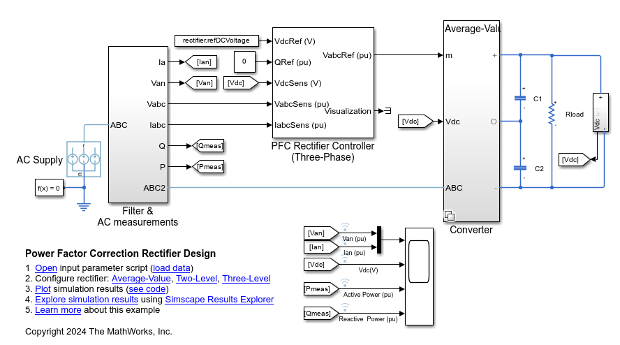
This example models a 100 kW, 60 Hz three-phase power factor correction converter, but you can edit these and other parameters by using the system input parameters script. To open this script, in the MATLAB® Command Window, enter this command.
edit 'PowerFactorCorrectionRectifierInputData'
This model uses a variant subsystem named Converter to switch between three different subsystems that model the converter. You can switch between the subsystems using variant controls. The Average-Value subsystem uses an Average-Value Voltage Source Converter (Three-Phase) block. You can use this model for a faster simulation without harmonics. To select this low-fidelity variant, set the powerCircuit variable to 0.

The Two-Level subsystem uses a Converter (Three-Phase) block. You can use this model to simulate harmonics. To select this variant, set the powerCircuit variable to 1.

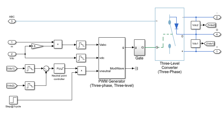
The Three-Level subsystem uses a Three-Level Converter block. You can use this model to simulate harmonics. To select this variant, set the powerCircuit variable to 2.
Plot Simulation Results
Load the input parameters.
PowerFactorCorrectionRectifierInputData;
To enable the Average-Value subsystem, set the powerCircuit variable to 0.
powerCircuit = 0;
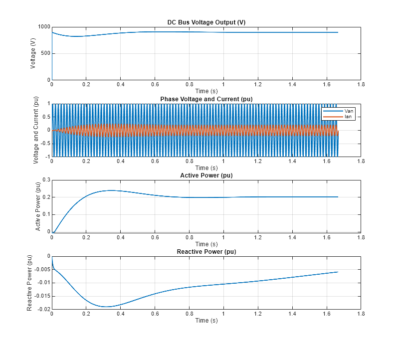
Plot the simulation results.
PowerFactorCorrectionRectifierPlot;
See Also
Blocks
Simscape Blocks
- Average-Value Voltage Source Converter (Three-Phase) | Converter (Three-Phase) | Three-Level Converter (Three-Phase)