Three-Phase Synchronous Machine Control
This example shows how to control and initialize a Synchronous Machine (SM). The test circuit shows the SM operating as a generator. The terminal voltage is controlled using an AVR and the speed is controlled using a governor.
To view the SM machine base values and initial conditions, double-click the Synchronous Machine Round Rotor (standard) block and, in the Utilities section, click the Display button next to the Base values, Associated base values, or Associated initial conditions parameters. The overall model is initialized to start in periodic steady state to supply a load of 250 MW/15 Mvar.
Open Model

View Simulation Results from Simscape Logging
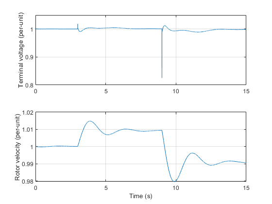
The plot below shows the terminal voltage and rotor velocity for the Synchronous Machine.
Results from Real-Time Simulation
This example has been tested on these platforms:
Speedgoat™ Performance real-time target machine with an Intel® 3.5 GHz i7 multi-core CPU and 4 GB RAM.
dSPACE® SCALEXIO LabBox with Intel® Core XEON E3-1275v3 at 3.5GHz and 4 GB RAM.
You can run this model in real time with a step size of 100 microseconds by using the Simscape local solver. For small sample rates, a task overrun might occur during the initial task execution due to a cold cache. To avoid this overrun, if the selected platform supports these options, relax the start-up behavior by specifying a limited number of task overruns or increasing the sample time of periodic tasks during the start-up phase of the real-time application.
See Also
Synchronous Machine Round Rotor | Wye-Connected Load | Circuit Breaker (Three Phase) | SM AC1C