Detect Objects Using Vision Sensor in Gazebo Simulator
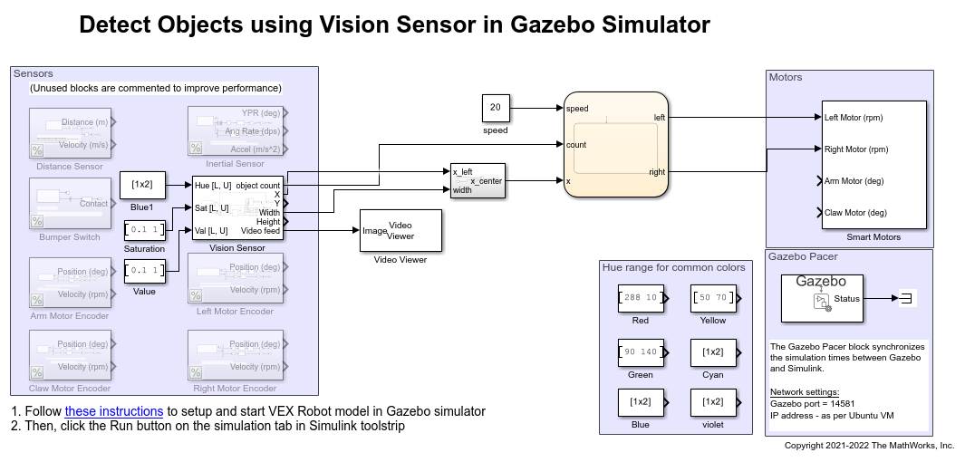
This example shows how to use a simulated vision sensor to detect colored objects in the field and perform actions based on it. This example uses a pre-configured Simulink® model created for Gazebo simulator (along with a virtual world). The robots control algorithm is modelled as a Stateflow® chart in Simulink. Simulink reads data from sensors and writes commands to motors in Gazebo using Gazebo co-simulation blocks.
Set up Gazebo Simulation Environment
To run this example, download and set up the preconfigured Virtual Machine with ROS and Gazebo. For more information, see Set Up Gazebo Simulation Environment. In the Setup Gazebo Simulation Environment topic, perform the steps listed in these topics.
Simulink Model
1. Open the vexv5_gzsim_vision_scan preconfigured Simulink example model.
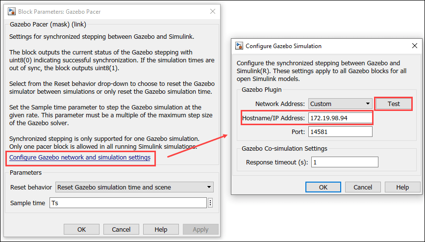
2. Navigate to VEX® V5 Robot interface/Gazebo Simulation Interface subsystem and Open Gazebo Pacer block.
3. Click Configure Gazebo network and simulation settings. Enter the Virtual machine IP Address. Set the Port to 14581.
4. Click Test connection to verify the connection to Gazebo model. Click Ok and close the block dialog.
Program Logic
The control algorithm of the robot is modeled in the vexv5_gzsim_vision_scan > chart Stateflow chart. Double-click the chart to view the program logic.
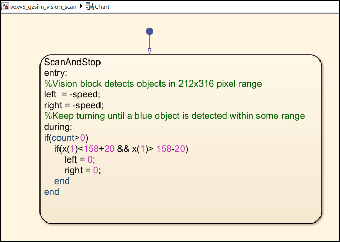
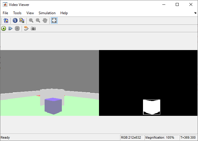
The robot keeps turning until a specific colored object is detected within a range. The Vision Sensor block detects the colored object.
Video feed from the simulated vision sensor can be seen with a video viewer block as shown below.
Simulate Model
In the preconfigured Simulink model, on the Simulation tab, click Run to simulate the model.
Other Things to Try
Count the number of blue objects around the robot.
Pick up an object solely using Vision sensor.
Detect objects of different colors.
See Also
You can also select a web site from the following list:
Americas
- América Latina (Español)
- Canada (English)
- United States (English)
Europe
- Belgium (English)
- Denmark (English)
- Deutschland (Deutsch)
- España (Español)
- Finland (English)
- France (Français)
- Ireland (English)
- Italia (Italiano)
- Luxembourg (English)
- Netherlands (English)
- Norway (English)
- Österreich (Deutsch)
- Portugal (English)
- Sweden (English)
- Switzerland
- United Kingdom (English)