Using eCAP Block in HRCAP Mode to Capture Input Signals
This example shows how to use high resolution mode (HRCAP) in eCAP block to capture the input signals using C2000™ Microcontroller Blockset.
In this example you will learn how to use eCAP in high resolution and normal resolution to capture the input pulse On and Off time.
Note:You can enable high resolution mode (HRCAP mode) using eCAP block for TI F28002x, F28003x, F28004x, F2838x, and F28P65x processors. For F2803x and F2806x processors use the HRCAP block. For more information, see Using HRCAP to Capture Input Signals
Prerequisites
Complete the following tutorials:
Required Hardware
TI F280025C LaunchPad or TI F28002x ControlCard
Available Models
c28xhrcaptype1.slx
Model
Open the c28xhrcaptype1.slx model.

Configure and Run HRCAP Model
1. Open the c28xhrcaptype1.slx model. This model is configured for TI F280025C LaunchPad hardware.
2. In this model, the output from ePWM1 and ePWM2 are routed to the input of eCAP1 and eCAP3 respectively using the Input X Bar. To run the model on other TI C2000 processors, first press Ctrl+E to open the Configuration Parameters dialog box. Then, select the required hardware board by navigating to Hardware Implementation > Hardware board.

Navigate to ePWM tab in Target hardware resources and check the pin assignment for PWM1A and PWM2A.

Go to eCAP in Target hardware resources and check the eCAP1 and eCAP3 input.
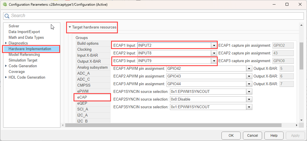
Go to Input X-BAR in Target hardware resources and assign the GPIO pins captured in ePWM1 and ePWM2 (GPIO0 and GPIO2) to eCAP input pins (INPUT2 and INPUT9).

3. Perform the peripherals configurations in the model as described in the Configure ePWM and eCAP Modules section. Use the same parameter values if you want to run this example for other hardware boards.
Configure ePWM and eCAP Modules
ePWM Block
1. Configure the ePWM1 and ePWM2 blocks to send the signal by configuring the Counting mode to Up and set the Timer initial period to 1e-4. The timer initial period values can be changed with the knob provided in the model.

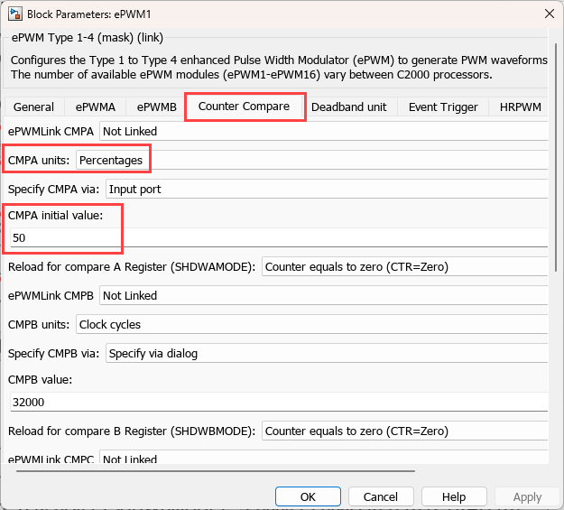
2. In the Counter compare tab, set CMPA units to Percentages and CMPA value to 50 to set the duty cycle to 50 %.
3. In the HRPWM tab, Select Enable high resolution period on ePWMxA (HRPWM-period).

eCAP Block
For eCAP block,
The eCAP1 block is configured in Normal mode to capture the ePWM1 output.
Set Stop value after to Capture event 2.
Select parameter Enable reset counter after capture event 1 time-stamp
Set Select capture event 1 polarity to Rising edge.
Select parameter Enable reset counter after capture event 2 time-stamp.
Set Capture event 2 polarity to Falling edge.

For eCAP3 block,
The eCAP3 block is configured in High resolution mode to capture the ePWM2 output.
Select parameter Enable high resolution capture.
Select parameter Enable continuous calibration mode.
Set the Calibration Period to 0.0016.
Set Select mode control to Continuous.
Set Output type to Microseconds.
Set Stop value after to Capture event 2, Select the parameter Enable reset counter after capture event 1 time-stamp, and set Capture event 1 polarity to *Rising edge.
Select parameter Enable reset counter after capture event 2 time-stamp and set *Capture event 2 polarity to *Falling edge.

Monitor Signals and Tune the Model
When you perform the Monitor & Tune action for the model, the host computer communicates with the target on which the generated executable runs.
1. On the Hardware tab of the model click Monitor & Tune.

2. Use the diagnostic viewer to follow the build progress and wait until the code loads and runs on the target hardware.
3. View the output in the Display block.
The Display block (Period in microseconds) value is captured by the eCAP time period in microseconds which was set for the ePWM block output.
As the duty cycle in ePWM block is configured to 50%, the On and Off value are 50% of the period. You can view the same in the captured value by the eCAP block.
4. Change the time Period and duty cycle in the ePWM blocks through the knob provided and observe the output.
Other Things to Try
Try to capture input signal given through function generator.