Using HRCAP to Capture Input Signals
This example shows how to use high resolution capture (HRCAP) Block to capture the input signals using C2000™ Microcontroller Blockset.
In this example you will learn how to use HRCAP in high resolution and normal resolution to capture the input pulse On and Off time.
Note:You can enable high resolution mode (HRCAP mode) using eCAP block for TI F28002x, F28003x, F28004x, F2838x, and F28P65x processors. For more, see C28x/C29x eCAP and Using eCAP Block in HRCAP Mode to Capture Input Signals.
Prerequisites
Complete the following tutorials:
Required Hardware
TI Piccolo F28069M LaunchPad or TI F2806x ControlCard
Hardware Connection

Available Models
c2806xhrcap.slx
Model
Open the c2806xhrcap.slx model.

Configure and Run HRCAP Model
1. Open the |c2806xhrcap.slx> model. This model is configured for TI Piccolo F28069M LaunchPad hardware.
2. To run the model on other TI C2000 processors, first press Ctrl+E to open the Configuration Parameters dialog box. Then, select the required hardware board by navigating to Hardware Implementation > Hardware board.
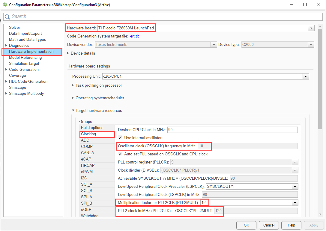
Navigate to Build options and disable Boot from flash.
Go to Clocking and ensure PLL2MULT and OSCCLK values are such that PLL2 clock value is 120.
Go to HRCAP > set HRCAP2 Pin assignment to
GPIO27and HRCAP1 Pin assignment toGPIO54.

3. Perform the peripherals configurations in the model as described in the Configure ePWM and HRCAP Modules section. Use the same parameter values if you want to run this example for other hardware boards.
Configure ePWM and HRCAP Modules
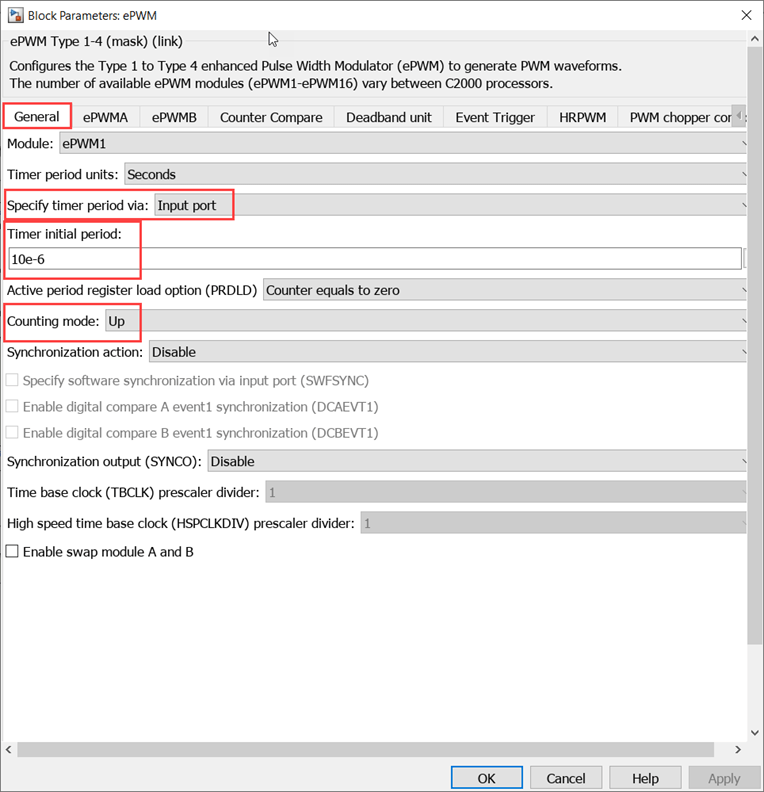
ePWM Block
Configure the ePWM1 and ePWM2 blocks to send the signal by configuring the Counting mode to
Upand set the Timer initial period to10e-6. The timer initial period values can be changed with the knob provided in the model.
In the Counter compare tab, set CMPA units to
Percentagesand CMPA value to50to set the duty cycle to 50 %.

In the HRPWM tab, Select Enable high resolution period on ePWMxA (HRPWM-period).

HRCAP Block
For HRCAP2 block , set HRCAP mode to
High resolution, Output type tofixdt(0,16,16), HRCAP output toAll above (Period, On time , Off time ).
Note: Fixed-Point Designer license is required when Output type is set to fixdt(0,16,16). If it is set to uint32, the data will be of Q16 format.
For HRCAP1 block, set the HRCAP mode to
Normaland Output type toMicroseconds.

Time Calculation in Microseconds
The HRCAP block in high resolution provides output values for Period, On time, and off time, which are expressed in HCCAPCLK cycles. To convert the period output to seconds, divide the number of HCCAPCLK cycles by the HRCAP clock frequency (which is PLL2CLK for high resolution). This calculation yields the output value in seconds.
In the model, the output values are calculated in microseconds.
HCCAPCLK cycles is the output value of HRCAP clock of Period, On , and Off time in high resolution mode and you can select output in normal mode to be in HCCAPCLK cycles or in microseconds.
HRCAP clock can be PLL clock or SYS clock.
Monitor Signals and Tune the Model
When you perform the Monitor & Tune action for the model, the host computer communicates with the target on which the generated executable runs.
1. On the Hardware tab of the model click Monitor & Tune.

2. Use the diagnostic viewer to follow the build progress and wait until the code loads and runs on the target hardware.
3. Observe the output in the Display block.
The Display block (Period in microseconds) value is captured by the eCAP time period in microseconds which was set for the ePWM block output.
As the duty cycle in ePWM block is configured to 50%, the On and Off value are 50% of the period. You can view the same in the captured value by the eCAP block.
4. Change the time Period and duty cycle in the ePWM blocks through the knob provided and observe the output.
Note: When working with the high frequency signals, the jumper connection may introduce an additional noise which may be reflected in the HRCAP output.
Other Things to Try
Try to capture input signal given through function generator.
Try using Hardware Interrupt block to capture input signals of frequency less than 1KHz. HCCOUNTER will overflow and Hardware Interrupt block can be used to capture number of overruns.