Submodules of ePWM Type 1-4
Several motor control and power electronics applications use the enhanced Pulse Width Modulator (ePWM) peripheral. C2000™ Microcontroller Blockset supports the following eight submodules of ePWM Type 1-4 block:
Time-Base
Counter Compare
Action Qualifier
Dead-Band Generator
PWM Chopper
Trip Zone
Event Trigger
Digital Compare
The diagram shows ePWM submodules from a Texas Instruments® Technical Reference Manual.

This tutorial provides you with an overview of the time-base, counter compare, action qualifier, trip zone, and digital compare submodules.
| submodules | Description | Configurations | Examples |
|---|---|---|---|
The time-base submodule enables configuring the period and mode at which ePWM counter operates, which in turn determines the period of the ePWM outputs. | Generate ePWM Waveform for Specified Frequency and Duty Cycle | ||
The counter compare submodule compares the time-base counter value with the counter compare registers and generates an appropriate event. | |||
The action qualifier submodule specifies the action to be taken on the ePWM output when time-base and counter compare events occur. | |||
Trip zone signals indicate external faults or trip conditions. | Implement Crossbar (X-BARs) Functionality with C2000 Microcontroller Blockset | ||
The digital compare submodule compares signals that are external to the ePWM block to directly generate PWM events. |
Time-Base
The time-base submodule enables you to configure the period and mode at which ePWM counter operates which in turn determines the period of the ePWM outputs.
This diagram shows time-base submodule signals and registers from a TI Technical Reference Manual.

The outputs of the time-base submodule are events when the time-base counter reaches the value of zero or the period (TBPRD). The output is dependent on the mode of the time-base counter. There are three counting modes:
Up-count: The time-base counter value starts from zero and increases until TBPRD is reached. Once the counter reaches TBPRD, the counter resets to zero.
Down-count: The time-base counter value starts from TBPRD and decreases until the value is zero. Once the counter reaches zero, the counter resets to TBPRD.
Up-down-count: The time-base counter value starts from zero and increases until TBPRD is reached. Once the counter reaches TBPRD, the counter decreases until it reaches zero.
In all of the counting modes, the counter then repeats the respective pattern in loop.
Time-base submodule controls time-base synchronization with other ePWM modules. You can configure time-base submodule to synchronize between multiple ePWM modules and to introduce phase shift between those ePWM modules. For more information, see Overview of Time-Base Synchronization in ePWM Type 4.
Configure Time-Base Submodule
Configuring time-base submodule involves these steps:
Configure the EPWM clock divider (EPWMCLKDIV) parameter.
Note
This parameter is available only with some TI C2000™ processors.
Navigate to Hardware Implementation > Target Hardware Resources > ePWM as shown here.

Configure Time base Clock (TBCLK), which is expressed as:
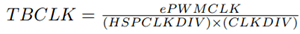
Configure Time base clock (TBCLK) prescaler divider and High speed time base clock (HSPCLKDIV) prescaler divider in the ePWM Type 1-4 block as shown below.
Note
The High speed time base clock (HSPCLKDIV) prescaler divider parameter is available only with some TI C2000™ processors.
Configure the timer period and the mode of operation:
The frequency of the ePWM output depends on how you configure TBCLK, TBPRD and Counting mode.
This diagram shows time-base frequency and period from a TI Technical Reference Manual.

Count Mode Timer period units Calculation Example Up or Down Clock cycles The value entered in clock cycles is used to calculate time-base period (TBPRD) for the ePWM timer register. The period of the ePWM timer TCTR = (TBPRD + 1) * TBCLK, where TCTR is the timer period in seconds, and TBCLK is the time-base clock.
For ePWM clock (EPWMCLK) frequency = 200 MHz and TBCLK = 5 ns.
EPWMCLK equals SYSCLKOUT or SYSCLKOUT/2 depending on the EPWM clock divider (EPWMCLKDIV) parameter setting.
When you specify the timer period in clock cycles TBPRD = 9999,the ePWM timer period is calculated as TCTR = 50 µs.
For the default action settings on the ePWMx tab, the ePWM period = 50 µs.
Seconds The value entered in seconds is used to calculate the time-base period (TBPRD) for the ePWM timer register. The TBPRD value entered in the register is TBPRD = (TCTR / TBCLK) – 1, where, TCTR is the timer period in seconds and TBCLK is the time-base clock.
For the default action settings on the ePWMx tab, the ePWM period is the same as the specified timer period (in seconds).
For EPWMCLK frequency = 200 MHz and TBCLK = 5 ns.
When you specify the timer period in seconds TCTR = 50 µs and the time based period is calculated as TBPRD = 9999.
For the default action settings in the ePWMx tab, the ePWM period = 50 µs.
Up-Down Clock cycles The value entered in clock cycles is used to calculate the time-base period (TBPRD) for the ePWM timer register. The period of the ePWM timer, TCTR = 2 * TBPRD * TBCLK, where TCTR is the timer period in seconds and TBCLK is the time-base clock.
For EPWMCLK frequency = 200 MHz and TBCLK = 5 ns.
When you specify the timer period in clock cycles, TBPRD = 10000, and the ePWM timer period is calculated as TCTR = 100 µs.
For the default action settings on the ePWMx tab, the ePWM period = 100 µs.
Seconds The value entered in seconds is used to calculate the time-base period (TBPRD) for the ePWM timer register. The TBPRD value entered in the register is TBPRD = TCTR / TBCLK, where TCTR is the timer period in seconds and TBCLK is the time-base clock.
For the default action settings on the ePWMx tab, the ePWM period is two times the specified timer period (in seconds).
For EPWMCLK frequency = 200 MHz and TBCLK = 5 ns.
When you specify the timer period in seconds TCTR = 50 µs, and the time based period is calculated as TBPRD = 10000.
For the default action settings on the ePWMx tab, the ePWM period = 100 µs.
The timer period value is fed through
Specify via dialogorInput port.Timer period units are either in
Clock cyclesorseconds.You can configure the timer period and counting mode parameters in the ePWM Type 1-4 block as shown here.

For example, in an F2837xD processor running at a frequency of 200 MHz, to achieve an ePWM output frequency of 10 kHz, the calculation is shown here.

You can configure the parameters of the ePWM Type 1-4 block based on the calculation as shown here.

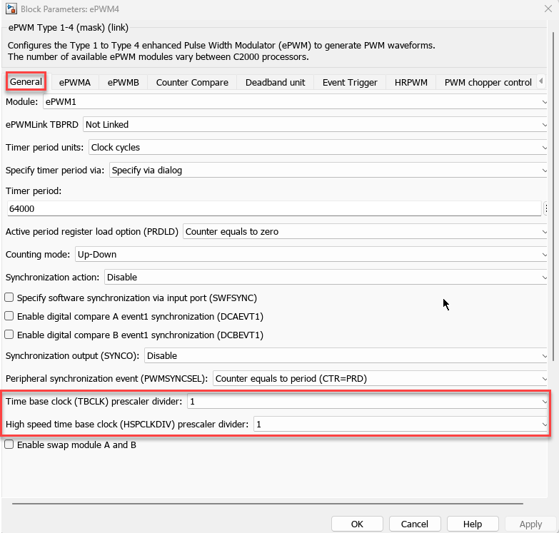
Configure shadow register:
The time-base period register has a shadow register. Shadowing allows the register update to be synchronized with the hardware. Shadowing also, it prevents corruption or spurious operation due to the register being asynchronously modified by the software.
Configure an event that writes the TBPRD to an active register from a shadow register using Active period register load option (PRDLD) in the ePMW Type 1-4 block as shown here.
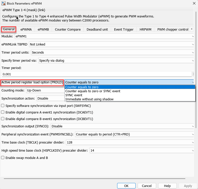
Configure ePWMLink TBPRD
For variable frequency applications, you must simultaneously write to TBPRD and CMPx registers between ePWM modules. This prevents situations where the counter value being zero or period results in some registers being loaded from new shadow values while others are loaded from old shadow values.
The ePWM TBPRD for a given ePWM module is linked with other ePWM modules using ePWMLink TBPRD in the ePMW Type 1-4 block as shown here.
You can configure the time-base submodule to synchronize between multiple ePWM modules and to introduce phase shift between those ePWM modules. For more information on phase synchronization parameters, see Overview of Time-Base Synchronization in ePWM Type 4.
You can configure these phase synchronization parameters in the ePWM Type 1-4 block.

Counter Compare
The time-base counter value is passed as input to the counter compare submodule. This value is continuously compared to the Counter Compare A (CMPA), Counter Compare B (CMPB), Counter Compare C (CMPC), and Counter Compare D (CMPD) registers. When the time-base counter value equals the value of one of the counter compare registers, the counter compare unit generates an appropriate event.
Configure Counter Compare Submodule
Configuring a counter compare submodule involves these steps:
Configure CMPx:
The CMPx units are either in
Clock cyclesorPercentagesin the ePWM Type 1-4 block as shown here.
The CMPx values are specified through
Input portorSpecify via dialogin the ePWM Type 1-4 block as shown here.
Configure an event to write the CMPx value to an active register from a shadow register using Reload for compare x Register (SHDWxMODE)
Configure ePWMLink CMPx to simultaneously write to CMPx registers between ePWM modules.
You can configure the Reload for compare x Register (SHDWxMODE) and ePWMLink CMPx parameters in ePWM Type 1-4 block as shown here.

Action Qualifier
Action qualifier and counter compare submodules together configure the duty cycle of the ePWM output waveform. Action qualifier specifies the action to be taken on the ePWM output when time-base and counter compare events occur.
Configure Action Qualifier Submodule
In the ePWM Type 1-4 block, two separate tabs ePWMA and ePWMB are provided to configure action qualifier settings for ePWMA and ePWMB outputs, respectively.
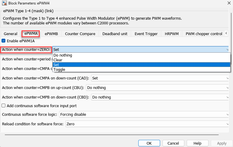
There are four actions that can occur when a counter compare event is matched:
Set: Drives the output high
Clear: Drives the output low
Toggle: Changes the state of the output
Do Nothing: The output remains unaffected
When the counter value is zero, configure the parameter in the ePWM Type 1-4 block as shown here.
For an example on how to generate a waveform of a given frequency and duty cycle using ePWM Type1-4 block, see Generate ePWM Waveform for Specified Frequency and Duty Cycle.
Trip Zone
Each ePWM module is connected to six trip zone signals (TZ1 to TZ6). TZ1 to TZ3 are sourced from the GPIO pins. TZ4 to TZ6 are sourced from internal signals. These signals indicate external faults or trip conditions.
This diagram shows a trip zone submodule from a TI Technical Reference Manual.

Trip Zone supports:
One-shot trip (OST) for major short circuits or over-current conditions.
Cycle-by-cycle (CBC) tripping for current limiting operation.
When trip zone detects an OST it drives the ePWM outputs to the specified state. The outputs remain in that trip state until you manually clear the trip.
When trip zone detects a CBC it drives the ePWM outputs to the specified state. The outputs return to its original state when the trip is released. The trip is released automatically when the trip reaches a certain state like zero or period.
Configure Trip Zone Submodule
Configuring the trip zone submodule involves these steps:
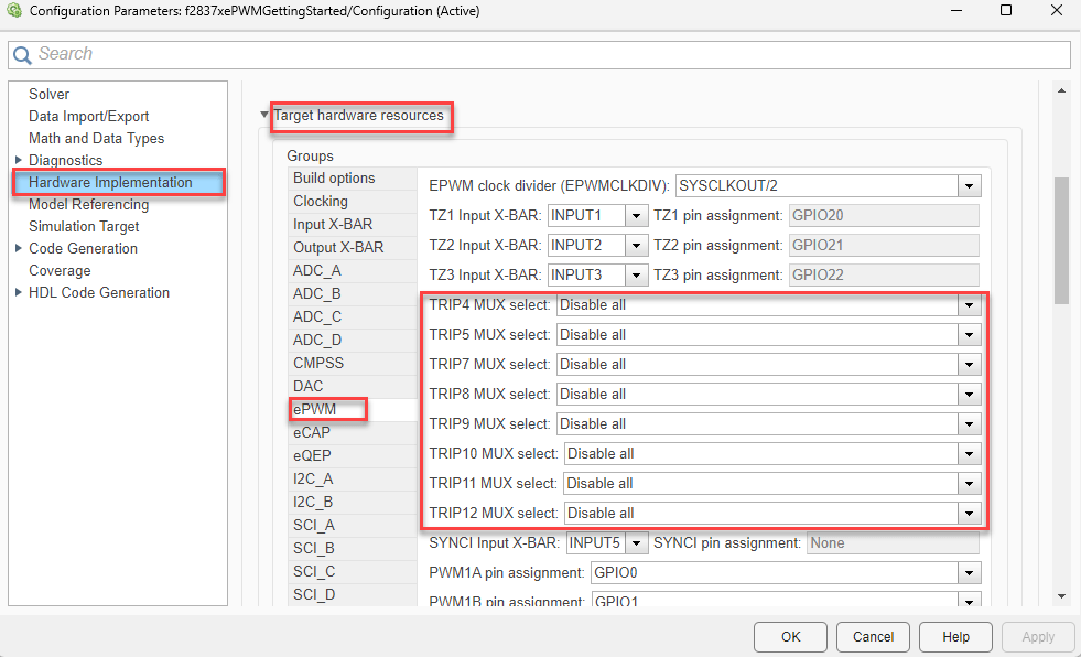
Configure the TZ1 to TZ3 signals that come from INPUT X-BAR1 to INPUT X-BAR3, respectively:
Navigate to Hardware Implementation > Target hardware resources > Input X-BAR to configure the GPIO pins for these signals as shown here.

Navigate to Hardware Implementation > Target hardware resources > ePWM to visualize the pin assignment as shown here.

Note
The Input X-BAR is not available for some of the TI C2000™ processors. For these processors you assign the GPIO pins are directly to the trip zone in the ePWM tab.

The Trip zone source signals are specified through
Input PortorSpecify via dialogin the ePWM Type 1-4 block as shown here.
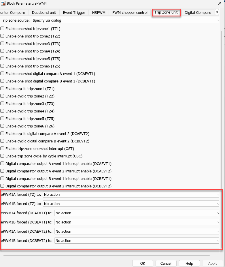
On enabling any cycle-by-cycle event, configure the event to clear the CBC trip using Clear cycle-by-cycle trip latch at in the ePWM Type 1-4 block as shown here.

You can generate interrupts on any trip-zone input. Configure the trip zone using the parameters in ePWM Type 1-4 block as shown here.

You can set the state of ePWM outputs to High, Low, High-impedence, or No action state on encountering a fault condition. Configure state using the parameters in ePWM Type 1-4 block as shown here.
Digital Compare
The digital compare submodule compares signals that are external to the ePWM block to directly generate PWM events. Blanking window functionality is present in this submodule to filter noise or unwanted pulses from the digital compare event signals.
In the digital compare submodule, the input signals TZ1 to TZ3 and TRIP6 come from the Input X-BAR via GPIO pins. TRIP14 and TRIP15 are internally generated input signals. TRIP4, TRIP5 and TRIP7 to TRIP12 are input signals that come from EPWM X-BAR. Select a combination of these signals to generate the Digital Compare A High and Low (DCAH/L) and Digital Compare B High and Low (DCBH/L) signals.
This diagram shows the digital compare submodule from a TI Technical Reference Manual.

Configure Digital Compare Submodule
Configuring digital compare submodule involves these steps:
Configure the trip signals from EPWM X-BAR.
Navigate to Hardware Implementation > Target hardware resources > ePWM as shown here.
Note
For some TI C2000™ processors, the trip numbers are different.
For more details on how to configure trip signals, see Implement Signal Routing Using C2000 Crossbar (X-BAR).
Configure the signals that come as Digital Compare A High/Low (DCAH/L) and Digital Compare B High/Low (DCBH/L) using the block parameters in the ePWM Type 1-4 block as shown here.

Configure the action qualifiers for the digital compare events DCAEVT1/2 and DCBEVT1/2 using the block parameters in the ePWM Type 1-4 block as shown here.

Once you enable a digital compare event, you can configure event filtering, blanking window, and counter capture using the block parameters in the ePWM Type 1-4 block as shown here.

Note
You can configure the digital compare events to force the ePWM outputs to trip in either of the two ways:
Pass the digital compare events directly as inputs to ePWMx Trip Logic.
Pass the digital compare events to EPWMx Trip Logic through an OST or CBC trip signal.
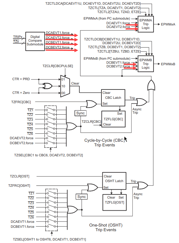
This diagram shows the digital compare and trip zone submodules from the TI Technical Reference Manual. In this diagram, the signal path for the scenario where you directly pass the digital compare events to ePWMx Trip Logic is highlighted in red.
You can configure the parameters of the ePWM Type 1-4 block for the scenario where you directly pass the digital compare events to ePWMx Trip Logic as shown here.

This diagram shows digital compare and trip zone submodules from a TI Technical Reference Manual. In this diagram, the signal path for the scenario where you pass the digital compare events to ePWMx Trip Logic through OST or CBC is highlighted in red.

You can configure the parameters of the ePWM Type 1-4 block for the scenario where you pass the digital compare events to ePWMx Trip Logic through OST or CBC as shown here.

See Also
ePWM Type 1-4 | Overview of Time-Base Synchronization in ePWM Type 4 | Generate ePWM Waveform for Specified Frequency and Duty Cycle | Implement Crossbar (X-BARs) Functionality with C2000 Microcontroller Blockset | Implement Signal Routing Using C2000 Crossbar (X-BAR)