Running Monitor & Tune Simulation over FTDI with Pixhawk 6x
In UAV Toolbox Support Package for PX4® Autopilots, serial communication is supported over the native-USB port and non-usb ports on the Pixhawk® Series boards. To achieve Monitor & Tune Simulation (External mode) over non-USB serial port, a serial-to-USB FTDI converter is required.
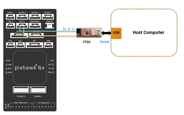
The below image shows the connection between GPS2 (/dev/ttyS7) on Pixhawk 6x board and the USB port on host computer, by using an FTDI converter.

The below table lists the serial pins of the GPS2 on the Pixhawk 6x board. The pins listed here are from left to right.
| Serial port mapping for GPS2 on Pixhawk 6x | |
|---|---|
| 1 | +5V |
| 2 | Tx |
| 3 | Rx |
| 4 | SCL2 |
| 5 | SDA2 |
| 6 | GND |
Connect the Rx an Tx of GPS2 port to the Tx and Rx of the FTDI device (Serial to USB Converter) respectively. Connect the FTDI device to host computer over another USB port.
Note the Host serial port for the FTDI (for example, COM7). In Windows operating system, you can find this in 'Device manager'.
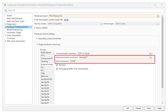
Once the above hardware connections are completed, open the Configuration Parameters
dialog box in Simulink®, and set the serial port to dev/ttyS7 (go to
Hardware Implementation pane > Target Hardware
Resources > External Mode, and enter
dev/ttyS7 in the Hardware board serial Port
field). Also enter the Host Serial port of your FTDI device in the Host Serial
Port dialog box. A sample screen is shown below.

Now you can run the model in Monitor & Tune Simulation over FTDI with Pixhawk 6x board.