Integrate Simulator Plant Model Containing MAVLink Blocks with Flight Controller Running on PX4 Host Target
The UAV Toolbox Support Package for PX4® Autopilots provides the option to simulate PX4 autopilot algorithms that you develop in Simulink®. The workflow is based on PX4 SITL (Software in the Loop). The support package supports simulation of algorithms by generating an executable on the host, PX4 Host Target, and the simulator designed in Simulink.
Introduction
PX4 supports running the PX4 flight code to control a computer-modeled vehicle in a simulated world (for more details, refer to this link). In this mode, the sensor data from the simulator is written to PX4 uORB topics. All motors and actuators are blocked, but internal PX4 software is fully operational. As described in the Simulator MAVLink API documentation, the PX4 flight stack and simulator exchange a specific set of MAVLink messages.
The PX4 flight stack sends motor and actuator values to the simulator using the HIL_ACTUATOR_CONTROLS MAVLink message. The simulator receives the HIL_ACTUATOR_CONTROLS message and sends the sensor, GPS, and quaternion data to the PX4 flight stack using HIL_SENSOR, HIL_GPS and HIL_STATE_QUATERNION MAVLink messages. These messages are exchanged via a TCP/IP connection as described here. The simulator is the TCP server on port 4560 and the PX4 host target is the client on the same IP address that connects to the server.
For details about how the PX4 Host Target simulates using the jMAVSim simulator, see Deployment and Verification Using PX4 Host Target and jMAVSim/Simulink.
Controller Model and Plant Model
To use the PX4 Host Target with the simulator plant designed in Simulink, follow a two-model approach.
Controller model — In this model, you use the sensors, attitude, and position data to design a controller and estimator and to output the motor and actuator values using the PX4 uORB Read block.
Simulator Plant model — In this model, you design the dynamics of the plant. Use the MAVLink Deserializer block to extract the HIL_ACTUATOR_CONTROLS message sent from the controller. The dynamics and sensors designed in the plant model output the sensors and attitude values to the MAVLink Serializer block in the form of HIL_SENSOR, HIL_GPS, and HIL_STATE_QUATERNION messages, and the block in turn sends the serialized data to TCP Send block.
Prepare Controller Model and Simulator Plant Model
Perform these steps, which are a part of the Hardware Setup process in the UAV Toolbox Support Package for PX4 Autopilots, to the enable PX4 Host Target.
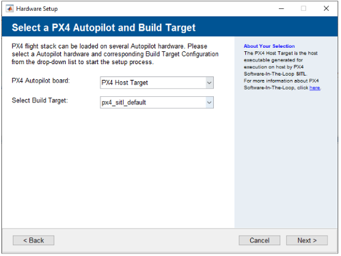
In the Select a PX4 Autopilot and Build Target Hardware Setup screen, select PX4 Host Target as the PX4 Autopilot board. The Build Target file is
px4_sitl_default.
Proceed with the subsequent steps in the Hardware Setup process to build the firmware and verify that the build was successful.
Prepare PX4 Host Target Controller Model
After completing the Hardware setup process, prepare the flight controller algorithm using the Simulink blocks available in the UAV Toolbox Support Package for PX4 Autopilots.
In the Modeling tab, click Model Settings.
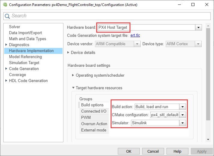
In the Configuration Parameters dialog box, choose
PX4 Host
                  Target
for the Hardware board.Go to Target hardware resources > Build Options, and choose
Build, load and runfor the Build action parameter.Choose
Simulinkfor the Simulator parameter.Click Apply and then OK.

Prepare the Simulator Plant Model
Use the MAVLink Deserializer block to extract the HIL_ACTUATOR_CONTROLS data sent from the controller model. Design the plant dynamics and send the data using MAVLink Serializer blocks to the controller model.
In the Simulation tab, click the Run button arrow then select Simulation Pacing.

In the Simulation Pacing Options dialog box, select Enable pacing to slow down simulation. For more information, see Simulation Pacing Options (Simulink).
Run the Controller and Simulator Plant Model
In the Controller Simulink model, go to the Hardware tab.
Set a value for the Simulation stop time parameter. The default value is 10.0 seconds. To run the model for an indefinite period, enter
inf.Click Monitor & Tune to run the model on external mode.
Simulink automatically creates a real-time connection between the model on the PX4 Host Target application and the model on the host computer.
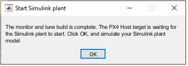
Wait for the code generation to be completed. Whenever the dialog box appears mentioning that the build is complete, ensure that you click OK.

Open the Simulator Plant model.
The Controller model is yet to start executing, and you can see the simulation time waiting at
0.000.In the Simulator Plant model, click Run to compare how both models execute in lockstep simulation.
Tip
If you encounter any performance issues while executing the two Simulink models, run the models in two separate MATLAB® sessions.
See Also
Monitor and Tune PX4 Host Target Flight Controller with Simulink-Based Plant Model