Simulate Flight Plan in Real-World Location Using Cesium
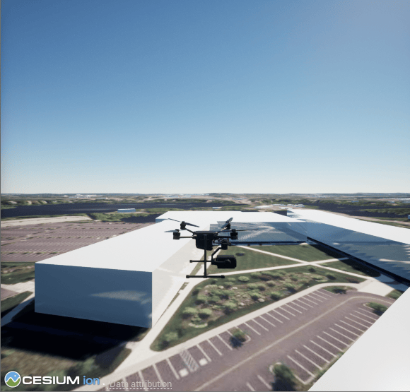
R2026bThis example shows how to simulate a flight plan created in QGroundControl in read-world location using Cesium Ion®.
The flight plan that this example uses is comprised of 4 waypoints that takes the quadcopter on a flight around the MathWorks® campus in Natick, Massachusetts.
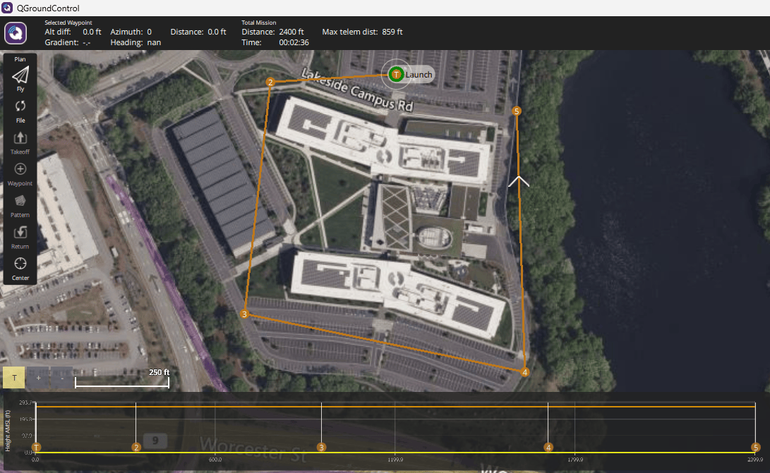
Generate Multirotor Trajectory from Flight Plan
To access the flight plan file and Simulink® model in this example, open the example live script by either clicking Open Live Script in the documentation or running openExample('uav/SimulateFlightPlanInRealWorldUsingCesiumExample').
% Create mission from flight plan file in the example.
M = uavMission(PlanFile="Survey_FlightPlan.plan");

% Show mission.
show(M);
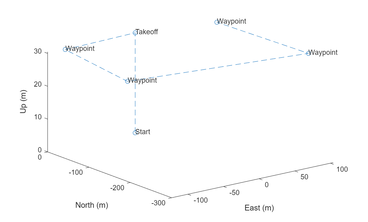
Create a multirotor UAV trajectory parser, and generate the trajectory.
parser = multirotorMissionParser;
trajectory = parse(parser,M);

% Show trajectory.
show(trajectory);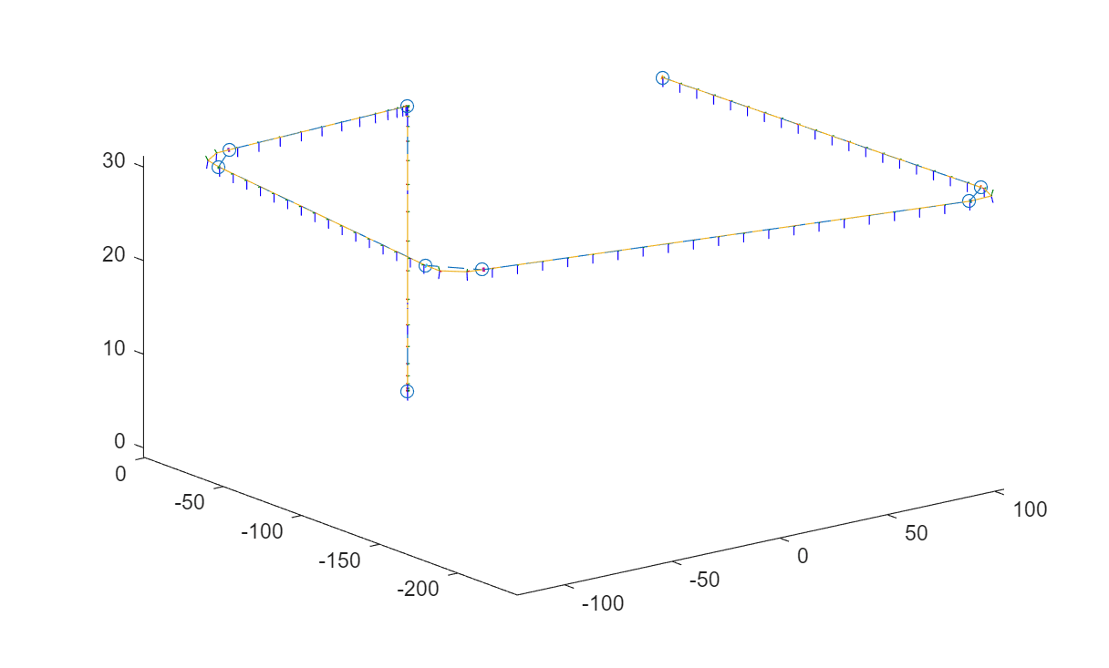
Visualize Flight Trajectory in Cesium
Open the FlightPlaninCesium.slx Simulink model.
open_system("FlightPlaninCesium.slx")The Simulink model contains "Read UAV Trajectory" block which generates translation and rotation samples for the 3D UAV Vehicle from the trajectory that you have created.
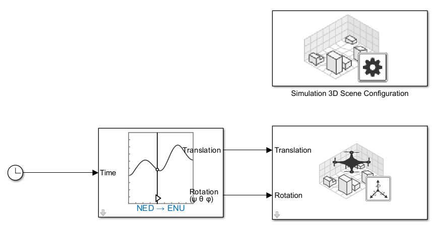
In the block parameter of the "Read UAV Trajectory" block, specify the Trajectory source as From trajectory object in workspace. Specify the Trajectory object as trajectory.
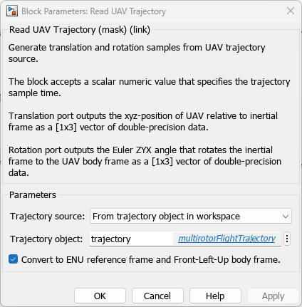
To visualize the trajectory in Cesium, first complete the steps in Visualize with Cesium if you have not already done so. The initial setup includes creating a Cesium Ion account and access token, and creating a new token in the Simulink Authentication Manager to hold your Cesium Ion token.
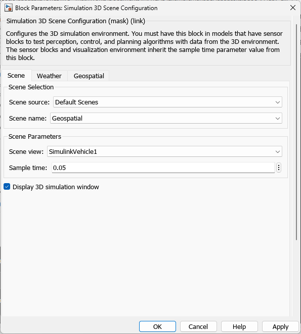
Specify the following parameters for the "Simulation 3D Scene Configuration Block":
In the Scene tab, select Scene Source as
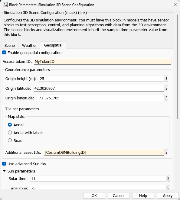
Default Scenes.In the Geospatial tab, select Enable geospatial configuration.
Enter your Cesium Ion token name in Access token ID.
Specify the Origin height, latitude, and longitude to match the takeoff coordinates.
To enable the OSM buildings in the visualization, populate the Additional asset ID with the Cesium OSM Building ID.
Select the Use advanced Sun sky.
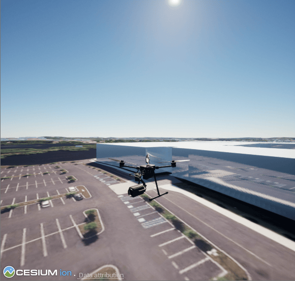
To start the simulation, select Run, then allow a few seconds for the 3D visualization window to initialize. Cesium Ion takes a few additional seconds for the 3D imagery to load.
See Also
Read UAV Trajectory | multirotorFlightTrajectory | uavMission

