Model Package Delivery with Custom Variable Mass 6DOF Block
This example shows, through incremental design iterations, how to implement a small multicopter simulation to take off, fly, and land in a city environment. A Custom Variable Mass 6DOF block is used to simulate the UAV package dropoff process.
UAV Package Delivery Model
This example builds upon on the model described in the UAV Package Delivery (UAV Toolbox) example, providing a variable mass model for simulating package dropoff dynamics. It also provides additional details on the plant model used to simulate the 6DOF vehicle dynamics.
Open the Project
Open the Simulink® project file to access the supporting files.
prj = openProject('asbPackageDelivery');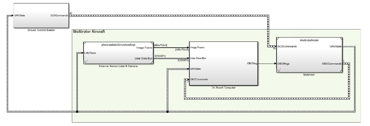
Model Architecture
The top model consists of the following subsystems and model references:
Ground Control Station - Control and monitor the aircraft while in-flight.
External Sensors - Lidar & Camera - Connect to previously-designed scenario or a photorealistic simulation environment. These sensors produce light detection and ranging (LIDAR) readings from the environment as the aircraft flies through it.
On Board Computer - Implement algorithms meant to run in an on-board computer independent from the Autopilot.
Multirotor - Include a multicopter model and flight controller, including its guidance logic.
The model design data is contained in a Simulink data dictionary in the data folder (asbPackageDeliveryDataDict.sldd). The model uses variant subsystems to manage different configurations of the model. Variables placed in the base workspace configure these variants without modifying the data dictionary. For more details on variant subsystems, see Variant Systems.
Step Through the Project Using Shortcuts
To step through the example, use the Project Shortcuts. Each shortcut sets up the required variables for the project.
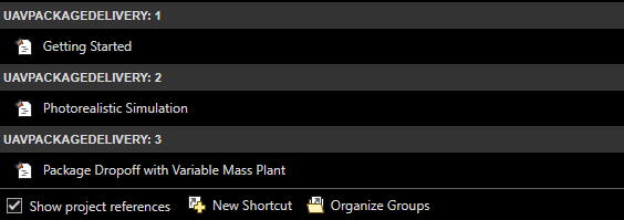
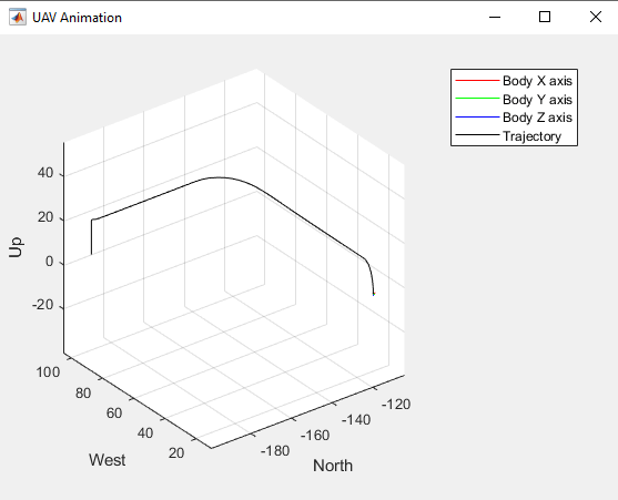
Getting Started
To set up the model for a four-waypoint mission, click the Getting Started project shortcut. Run the asbPackageDelivery model, which shows the multirotor take off, fly, and land in a 3-D plot.
The model uses the UAV Path Manager block to determine which is the active waypoint throughout the flight. The active waypoint is passed into the Guidance Mode Selector Stateflow® chart to generate the necessary inner loop control commands.
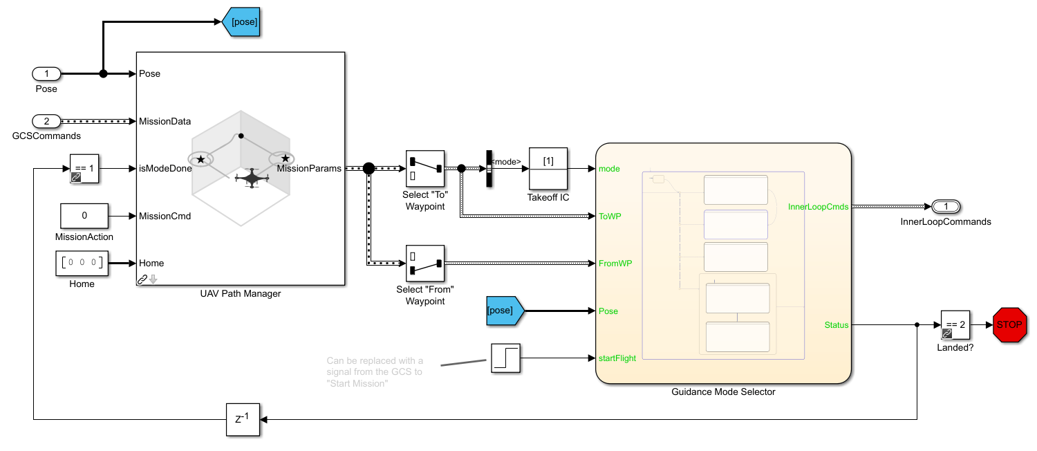
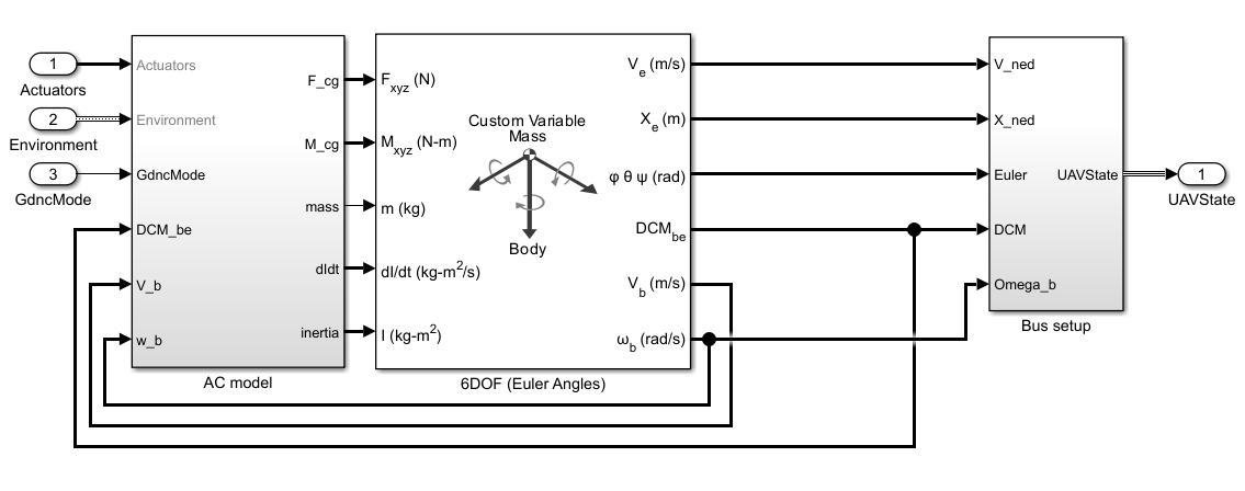
The UAV flight dynamics are modeled using a Custom Variable Mass 6DOF block, which accepts inputs for forces, moments, and mass properties. The model calculates forces arising from gravity, drag, and the motor, with the motor torque being provided as an external moment. During this simulation phase, mass, inertia, and the rate of change of inertia are treated as constants. The resulting UAV state is fed back into the controller, which then computes the necessary motor commands to ensure the UAV follows the designated waypoint.
Photorealistic Simulation
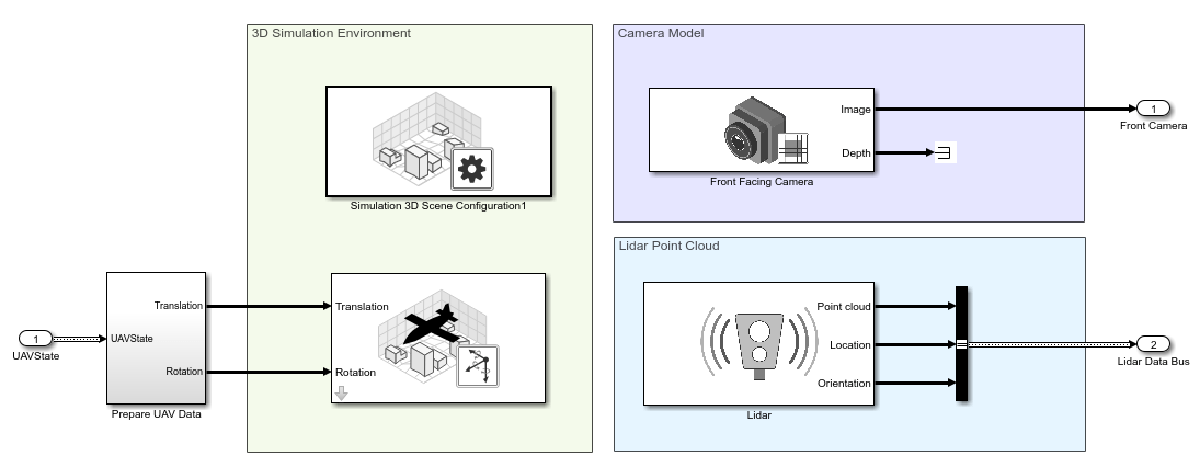
Up to this point, the environment is a simple cuboid scenario. To increase the fidelity of the environment, click the Photorealistic Simulation shortcut. This shortcut places the aircraft in a more realistic world to fly through. The PhotorealisticQuadrotor variant located at asbPackageDelivery/photorealisticSimulationEngi/SimulationEnvironmentVariant becomes active. This variant contains the necessary blocks to configure the simulation environment and the sensors mounted on the aircraft:
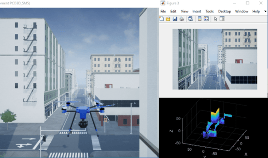
Run the model. The aircraft flies the same mission from step 1. Notice that as the aircraft flies the mission, an image from the front-facing camera is shown.
Add a Variable Mass 6DOF Plant Model for Modeling Package Dropoff
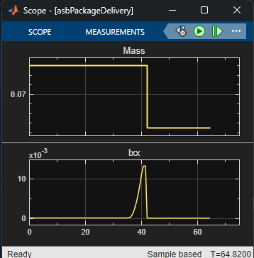
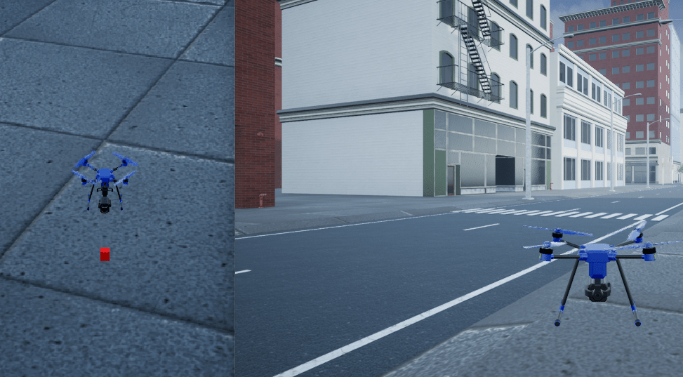
To load the dropoffMission with a custom waypoint for package dropoff modeling, click the Adding a Variable Mass Plant shortcut. The UAV flies to a designated delivery point and maintains position while the vehicle mass, inertia, and rate of change of inertia adjust to simulate lowering and releasing the package. A camera view follows the vehicle from in front to show both the vehicle and the package.
Upon reaching the dropoff point at an altitude of 1.5 meters, the package is lowered at a rate of 0.2 meters per second using a rigid arm with negligible mass. The changes in the x- and y-axis moment of inertia are modeled using the parallel axis theorem. Once the package is fully lowered to the ground, its mass and inertia are subtracted from the plant mass and inertia.
The mass properties of the UAV and the package are stored in the Vehicle and Package structs within asbPackageDeliveryDataDict.sldd. These properties can be modified to simulate vehicles and packages of varying sizes and dropoff speeds.
After completing delivery, the UAV proceeds to a designated landing point.
When you are done exploring the models, close the project file.
close(prj);
See Also
Custom Variable Mass 6DOF (Euler Angles)