comm.PSKDemodulator
(To be removed) Demodulate using M-ary PSK method
comm.PSKDemodulator will be removed in a future release. Use pskdemod instead. For information on updating your code, see Version History.
Description
The comm.PSKDemodulator object demodulates a signal that was modulated using
the M-ary phase shift keying (M-PSK) method. The input is a baseband representation of
the modulated signal.
To demodulate a signal that was modulated using the M-PSK method:
Create the
comm.PSKDemodulatorobject and set its properties.Call the object with arguments, as if it were a function.
To learn more about how System objects work, see What Are System Objects?
Creation
Syntax
Description
mpskdemod = comm.PSKDemodulator creates a System object™ to demodulate input M-PSK signals.
mpskdemod = comm.PSKDemodulator(
sets properties using one or more name-value arguments. For example,
Name=Value)DecisionMethod="Hard decision" specifies demodulation
using the hard-decision method.
mpskdemod = comm.PSKDemodulator(M,
sets the Name=Value)ModulationOrder
property to M and optional name-value arguments.
mpskdemod = comm.PSKDemodulator(M,phase,
sets the Name=Value)ModulationOrder
property to M, the PhaseOffset property
to phase, and optional name-value arguments. Specify
phase in radians.
Properties
Unless otherwise indicated, properties are nontunable, which means you cannot change their
values after calling the object. Objects lock when you call them, and the
release function unlocks them.
If a property is tunable, you can change its value at any time.
For more information on changing property values, see System Design in MATLAB Using System Objects.
Number of points in signal constellation, specified as a positive integer.
Data Types: double
Phase of the zeroth point in the constellation in radians, specified as a scalar.
Example: PhaseOffset=0 aligns the QPSK signal
constellation points on the axes {(1,0), (0,j), (-1,0),
(0,-j)}.
Data Types: double
Option to output data as bits, specified as a logical 0
(false) or 1
(true).
Set this property to
falseto output symbols as integer values in the range [0, (M – 1)] with length equal to the input data vector. M represents the value of theModulationOrder.Set this property to
trueto output a column vector of bit values with length equal to log2(M) times the number of demodulated symbols. Groups of log2(M) bits are mapped onto a symbol, with the first bit representing the MSB and the last bit representing the LSB.
Data Types: logical
Symbol encoding mapping of constellation bits, specified as
'Gray', 'Binary', or
'Custom'. Each integer or group of log2(ModulationOrder) bits corresponds to one symbol.
When you set this property to
'Gray', the object map symbols to a Gray-encoded signal constellation.When you set this property to
'Binary', the object map symbols to a natural binary-encoded signal constellation. Specifically, the complex value ej(PhaseOffset+ (2πm/ModulationOrder)), where m is an integer in the range [0, (ModulationOrder–1)].When you set this property to
'Custom', the object map symbols to the signal constellation defined in theCustomSymbolMappingproperty.
Custom symbol encoding, specified as an integer vector with length equal
to the value of ModulationOrder and unique values in the range
[0, (ModulationOrder – 1)]. The first element
of this vector corresponds to the constellation point at an angle of
0 + PhaseOffset, with
subsequent elements running counterclockwise. The last element corresponds
to the constellation point at an angle of –2π/ModulationOrder + PhaseOffset.
Dependencies
To enable this property, set the SymbolMapping property to 'Custom'.
Data Types: double
Demodulation decision method, specified as 'Hard
decision', 'Log-likelihood ratio', or
'Approximate log-likelihood ratio'. When you set the
BitOutput property
to false, the object always performs hard-decision
demodulation.
Dependencies
To enable this property, set the BitOutput
property to true.
Source of noise variance, specified as 'Property' or
'Input port'.
Dependencies
To enable this property, set the BitOutput
property to true and the DecisionMethod property to 'Log-likelihood
ratio' or 'Approximate log-likelihood
ratio'.
Noise variance, specified as a positive scalar.
Tunable: Yes
Tips
The exact LLR algorithm computes exponentials using finite precision arithmetic. For computations involving very large positive or negative magnitudes, the exact LLR algorithm yields:
Infor-Infif the noise variance is a very large valueNaNif the noise variance and signal power are both very small values
The approximate LLR algorithm does not compute exponentials. You can avoid
Inf, -Inf, and NaN results by using
the approximate LLR algorithm.
Dependencies
To enable this property, set the BitOutput
property to true, the DecisionMethod property to 'Log-likelihood
ratio' or 'Approximate log-likelihood
ratio', and the VarianceSource property to
'Property'.
Data Types: double
Data type of the output, specified as 'Full precision',
'Smallest unsigned integer',
'double', 'single',
'int8', 'uint8',
'int16', 'uint16',
'int32', or
'uint32','logical'.
When the input data type is single or double precision and you set the
BitOutputproperty totrue, theDecisionMethodproperty to'Hard decision', and theOutputDataTypeproperty to'Full precision', the output has the same data type as that of the input.When the input data is of a fixed-point type, the output data type behaves as if you had set the
OutputDataTypeproperty to'Smallest unsigned integer'.When you set
BitOutputtotrueand theDecisionMethodproperty to'Hard Decision', then'logical'data type is a valid option.When you set the
BitOutputproperty totrueand theDecisionMethodproperty to'Log-likelihood ratio'or'Approximate log-likelihood ratio', the output data type is the same as that of the input and the input data type must be single or double precision.
Dependencies
To enable this property, set the BitOutput
property to false or set the
BitOutput property to true
and the DecisionMethod property to 'Hard
decision'.
Fixed-Point Properties
Data type of the derotate factor, specified as 'Same word length
as input' or 'Custom'. The object uses the
derotate factor in the computations only when the ModulationOrder property is 2,
4, or 8, the input signal is a
fixed-point type, and the PhaseOffset
property has a nontrivial value.
For
ModulationOrder=2, the phase offset is trivial if it is a multiple of π/2.For
ModulationOrder=4, the phase offset is trivial if it is an even multiple of π/4.For
ModulationOrder=8, there are no trivial phase offsets.
Dependencies
To enable this property, set the BitOutput
property to false or set the BitOutput property to true and the
DecisionMethod property to 'Hard
decision'.
Fixed-point data type of the derotate factor, specified as an unscaled
numerictype (Fixed-Point Designer) object with a
Signedness of Auto. The word
length must be a value in the range [2, 128].
Dependencies
To enable this property, set the DerotateFactorDataType property to
'Custom'.
Data Types: numerictype object
Usage
Description
y = mpskdemod(x,var)var. This
syntax applies when you set the BitOutput property to
true, the DecisionMethod
property to 'Approximate log-likelihood ratio' or
'Log-likelihood ratio', and the VarianceSource
property to 'Input port'.
Input Arguments
M-PSK-modulated signal, specified as a scalar or column vector.
Dependencies
The object accepts inputs with a signed integer data type or
signed fixed point (sfi (Fixed-Point Designer)) objects when
you set the ModulationOrder property to a value less than or
equal to 8 and you set the BitOutput
property to false or you set the DecisionMethod property to 'Hard
decision' and the BitOutput property to
true.
Data Types: double | single | int | fi
Noise variance, specified as a scalar.
Dependencies
To enable this argument, set the VarianceSource property to 'Input
port', the BitOutput
property to true, and the DecisionMethod property to 'Approximate
log-likelihood ratio' or 'Log-likelihood
ratio'.
Data Types: single | double
Output Arguments
Output signal, returned as a scalar or column vector. To specify
whether the object outputs values as integers or bits, use the BitOutput
property. To specify the output data type, use the OutputDataType property.
Object Functions
To use an object function, specify the
System object as the first input argument. For
example, to release system resources of a System object named obj, use
this syntax:
release(obj)
constellation | Calculate or plot ideal signal constellation |
Examples
Create 16-PSK modulator and demodulator System objects that use custom symbol mapping. Estimate the BER in an AWGN channel and compare the performance to a theoretical Gray-coded PSK system.
Create a custom symbol mapping for the 16-PSK modulation scheme. The 16 integer symbols must have values in the range [0, 15].
custMap = [0 2 4 6 8 10 12 14 15 13 11 9 7 5 3 1];
Create a 16-PSK modulator and demodulator pair having custom symbol
mapping defined by the array custMap.
pskModulator = comm.PSKModulator(16,'BitInput',true, ...
    'SymbolMapping','Custom','CustomSymbolMapping',custMap);
pskDemodulator = comm.PSKDemodulator(16,'BitOutput',true, ...
    'SymbolMapping','Custom','CustomSymbolMapping',custMap);
Create an AWGN channel System object for use with 16-ary data.
awgnChannel = comm.AWGNChannel('BitsPerSymbol',log2(16));Create an error rate object to track the BER statistics.
errorRate = comm.ErrorRate;
Initialize the simulation vectors. Vary from 6 to 18 dB in 1 dB steps.
ebnoVec = 6:18;
ber = zeros(size(ebnoVec));
Estimate the BER by modulating binary data, passing it through an AWGN channel, demodulating the received signal, and collecting the error statistics.
for n = 1:length(ebnoVec)

    % Reset the error counter for each Eb/No value
    reset(errorRate)
    % Reset the array used to collect the error statistics
    errVec = [0 0 0];
    % Set the channel Eb/No
    awgnChannel.EbNo = ebnoVec(n);

    while errVec(2) < 200 && errVec(3) < 1e7
        % Generate a 1000-symbol frame
        data = randi([0 1],4000,1);
        % Modulate the binary data
        modData = pskModulator(data);
        % Pass the modulated data through the AWGN channel
        rxSig = awgnChannel(modData);
        % Demodulate the received signal
        rxData = pskDemodulator(rxSig);
        % Collect the error statistics
        errVec = errorRate(data,rxData);
    end

    % Save the BER data
    ber(n) = errVec(1);
end
Generate theoretical BER data for an AWGN channel using the berawgn function.
berTheory = berawgn(ebnoVec,'psk',16,'nondiff');
Use this code to plot the simulated and theoretical results. The 16-PSK modulation BER performance of the simulated custom symbol mapping is not as good as the theoretical prediction curve for Gray codes.
figure
semilogy(ebnoVec,[ber; berTheory])
xlabel('Eb/No (dB)')
ylabel('BER')
grid
legend('Simulation','Theory','location','ne')
More About
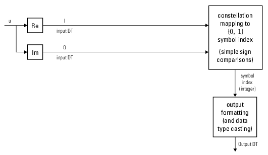
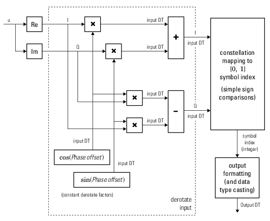
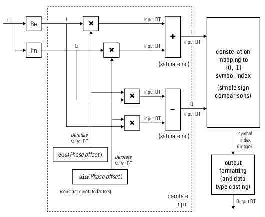
The signal preprocessing required for BPSK demodulation depends on the configuration.
This figure shows the hard-decision BPSK demodulation signal diagram for the trivial phase offset (multiple of π/2) configuration.
This figure shows the hard-decision BPSK demodulation floating-point signal diagram for the nontrivial phase offset configuration.
This figure shows the hard-decision BPSK demodulation fixed-point signal diagram for the nontrivial phase offset configuration.
The signal preprocessing required for QPSK demodulation depends on the configuration.
This figure shows the hard-decision QPSK demodulation signal diagram for the trivial phase offset (odd multiple of π/4) configuration.

This figure shows the hard-decision QPSK demodulation floating-point signal diagram for the nontrivial phase offset configuration.

This figure shows the hard-decision QPSK demodulation fixed-point signal diagram for the nontrivial phase offset configuration.

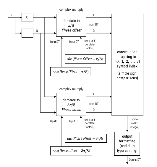
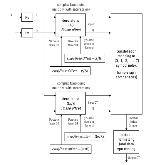
The signal preprocessing required for higher order PSK demodulation depends on the configuration.
This figure shows the hard-decision 8-PSK demodulation signal diagram for the trivial phase offset (odd multiple of π/8) configuration.
This figure shows the hard-decision 8-PSK demodulation fixed-point signal diagram for trivial phase offset (odd multiple of π/8) configuration.
This figure shows the hard-decision M-PSK demodulation floating-point signal diagram for the nontrivial phase offset configuration.
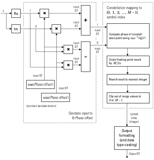
For M > 8, to improve speed and implementation costs, no derotation arithmetic is performed for trivial case (specifically, when phase offset is 0, π/2, π, or 3π/2).
Also, for M > 8, only double and
single input types are supported.
For soft demodulation, two soft-decision log-likelihood ratio (LLR) algorithms are available: exact LLR and approximate LLR. The exact LLR algorithm is more accurate but has slower execution speed than the approximate LLR algorithm. For further description of these algorithms, see the Hard- vs. Soft-Decision Demodulation topic.
Note
The exact LLR algorithm computes exponentials using finite precision arithmetic. For computations involving very large positive or negative magnitudes, the exact LLR algorithm yields:
Infor-Infif the noise variance is a very large valueNaNif the noise variance and signal power are both very small values
The approximate LLR algorithm does not compute exponentials. You can avoid
Inf, -Inf, and NaN results by using
the approximate LLR algorithm.
References
[1] Proakis, John G. Digital Communications. 4th ed. New York: McGraw Hill, 2001.
Extended Capabilities
Usage notes and limitations:
See System Objects in MATLAB Code Generation (MATLAB Coder).
The software supports double and
single data types for simulation, but not for HDL code generation.
To generate HDL code from predefined System objects, see Generate HDL Code for IIR Filter (DSP HDL Toolbox).
Version History
Introduced in R2012acomm.PSKDemodulator issues a warning that it will be removed in a future
release. Use the pskdemod function to M-ary PSK
demodulate the input signal.
comm.PSKDemodulator will be removed in a future release. Runs without
warning.
See Also
Functions
Objects
Blocks
MATLAB Command
You clicked a link that corresponds to this MATLAB command:
Run the command by entering it in the MATLAB Command Window. Web browsers do not support MATLAB commands.
Select a Web Site
Choose a web site to get translated content where available and see local events and offers. Based on your location, we recommend that you select: .
You can also select a web site from the following list
How to Get Best Site Performance
Select the China site (in Chinese or English) for best site performance. Other MathWorks country sites are not optimized for visits from your location.
Americas
- América Latina (Español)
- Canada (English)
- United States (English)
Europe
- Belgium (English)
- Denmark (English)
- Deutschland (Deutsch)
- España (Español)
- Finland (English)
- France (Français)
- Ireland (English)
- Italia (Italiano)
- Luxembourg (English)
- Netherlands (English)
- Norway (English)
- Österreich (Deutsch)
- Portugal (English)
- Sweden (English)
- Switzerland
- United Kingdom (English)