Sensor Fusion Using Synthetic Radar and Vision Data in Simulink
This example shows how to implement a synthetic data simulation for tracking and sensor fusion in Simulink® with Automated Driving Toolbox™. It closely follows the Sensor Fusion Using Synthetic Radar and Vision Data MATLAB® example.
Introduction
Simulating synthetic radar and vision detections provides the ability to create rare and potentially dangerous events and test the vehicle algorithms with them. This example covers the entire synthetic data workflow in Simulink.
Setup and Overview of the Model
Prior to running this example, the Driving Scenario Designer app was used to create the same scenario defined in Sensor Fusion Using Synthetic Radar and Vision Data. The roads and actors from this scenario were then saved to the scenario file OpenLoop.mat.
The Scenario Reader block reads the actor pose data from the saved file. The block converts the actor poses from the world coordinates of the scenario into ego vehicle coordinates. The actor poses are streamed on a bus generated by the block.
The actor poses are used by the Sensor Simulation subsystem, which generates synthetic radar and vision detections. The simulated detections are concatenated at the input to the Multi-Object Tracker block, whose output is a list of confirmed tracks. Finally, the Bird's-Eye Scope visualizes the actors, the vision and radar detections, the confirmed tracks and the road boundaries. The following sections describe the main blocks of this model.
open_system('SyntheticDataSimulinkExample');
Simulating Sensor Detections
In this example, you simulate an ego vehicle that has 6 radar sensors and 2 vision sensors covering the 360 degrees field of view. The sensors have some overlap and some coverage gap. The ego vehicle is equipped with a long-range radar sensor and a vision sensor on both the front and the back of the vehicle. Each side of the vehicle has two short-range radar sensors, each covering 90 degrees. One sensor on each side covers from the middle of the vehicle to the back. The other sensor on each side covers from the middle of the vehicle forward.
When you open the Sensor Simulation subsystem, you can see the two Vision Detection Generator blocks, configured to generate detections from the front and the back of the ego vehicle. The output from the vision detection generators is connected to a Detection Concatenation block. Next, the subsystem contains six Driving Radar Data Generator blocks, configured as described in the previous paragraph. The outputs of the radar data generators are configured to report the clustered centroid of the detections generated from each target.
open_system('SyntheticDataSimulinkExample/Sensor Simulation')
Tracking and Sensor Fusion
The detections from the vision and radar sensors must first be concatenated to form a single input to the Multi-Object Tracker block. The concatenation is done using an additional Detection Concatenation block.
The Multi-Object Tracker block is responsible for fusing the data from all the detections and tracking the objects around the ego vehicle. The multi-object tracker is configured with the same parameters that were used in the corresponding MATLAB example, Sensor Fusion Using Synthetic Radar and Vision Data. The output from the Multi-Object Tracker block is a list of confirmed tracks.
Creating and Propagating Buses
The inputs and outputs from the various blocks in this example are all Simulink.Bus (Simulink) objects. To simplify compiling the model and creating the buses, all the Vision Detection Generator, Driving Radar Data Generator, Multi-Object Tracker, and Detection Concatenation blocks have a property that defines the source of the output bus name. When set to 'Auto', the buses are created automatically and their names are propagated to the block that consumes this bus as an input. When set to 'Property', you can define the name of the output bus. The following images show the detections bus, a single detection bus, the tracks bus, and a single track bus.


Display
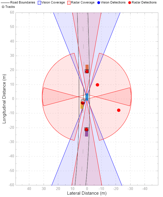
The Bird's-Eye Scope is a model-level visualization tool that you can open from the Simulink toolstrip. On the Simulation tab, under Review Results, click Bird's-Eye Scope. After opening the scope, click Find Signals to set up the signals. Then run the simulation to display the actors, vision and radar detections, tracks, and road boundaries. The following image shows the bird's-eye scope for this example.
close_system('SyntheticDataSimulinkExample')See Also
Apps
Blocks
- Detection Concatenation | Multi-Object Tracker | Driving Radar Data Generator | Vision Detection Generator