dsp.IIRHalfbandInterpolator
Interpolate by a factor of two using polyphase IIR
Description
The dsp.IIRHalfbandInterpolator
System object™ performs efficient polyphase interpolation of the input signal by a factor of
two. To design the halfband filter, you can specify the object to use an elliptic design or a
quasi-linear phase design. The object uses these design methods to compute the filter
coefficients. To filter the inputs, the object uses a polyphase structure. The allpass filters
in the polyphase structure are in a minimum multiplier form.
Elliptic design introduces nonlinear phase and creates the filter using fewer coefficients than quasi linear design. Quasi-linear phase design overcomes phase nonlinearity at the cost of additional coefficients.
Alternatively, instead of designing the halfband filter using a design method, you can specify the filter coefficients directly. When you choose this option, the allpass filters in the two branches of the polyphase implementation can be in a minimum multiplier form or in a wave digital form.
You can also use dsp.IIRHalfbandInterpolator object to implement the
synthesis portion of a two-band filter bank to synthesize a signal from lowpass and highpass
subbands.
To upsample and interpolate your data:
Create the
dsp.IIRHalfbandInterpolatorobject and set its properties.Call the object with arguments, as if it were a function.
To learn more about how System objects work, see What Are System Objects?
Creation
Syntax
Description
iirhalfbandinterp = dsp.IIRHalfbandInterpolator returns an IIR
halfband interpolation filter, iirhalfbandinterp, with the default
settings. Under the default settings, the System object upsamples and interpolates the input data using a halfband frequency of
22050 Hz, a transition width of 4100 Hz, and a
stopband attenuation of 80 dB.
iirhalfbandinterp = dsp.IIRHalfbandInterpolator(PropertyName=Value)Name-Value pair arguments.
Example: iirhalfbandinterp = dsp.IIRHalfbandInterpolator(Specification="Filter
order and stopband attenuation") creates an IIR halfband interpolator object
with filter order set to 9 and stopband attenuation set to
80 dB.
Properties
Usage
Description
y = iirhalfbandinterp(x1,x2)x1 and
x2. x1 is the lowpass output of a halfband
analysis filter bank and x2 is the highpass output of a halfband
analysis filter bank. dsp.IIRHalfbandInterpolator implements a synthesis
filter bank only when the FilterBankInputPort property is
true.
Input Arguments
Output Arguments
Object Functions
To use an object function, specify the
System object as the first input argument. For
example, to release system resources of a System object named obj, use
this syntax:
release(obj)
Examples
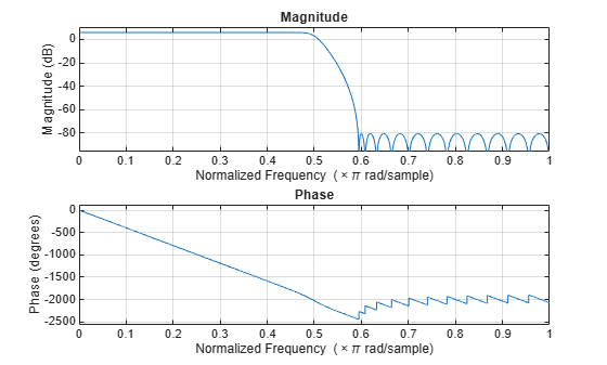
Create a minimum order lowpass IIR halfband interpolation filter. The filter has a transition width of 0.0930 in normalized frequency units, and a stopband attenuation of 80 dB.
IIRHalfbandInterp = dsp.IIRHalfbandInterpolator(...
    NormalizedFrequency=true,...
    DesignMethod="Quasi-linear phase");
Obtain filter coefficients
c = coeffs(IIRHalfbandInterp);
Plot the Magnitude and Phase response
freqz(IIRHalfbandInterp)
Design an elliptic IIR halfband interpolator object of order 31 and a transition width of 0.1 using the designHalfbandIIR function. Set the Verbose argument to true.
hbIIR = designHalfbandIIR(FilterOrder=31,TransitionWidth=0.1,DesignMethod="ellip",...
    Structure='interp',SystemObject=true,Verbose=true)
designHalfbandIIR(FilterOrder=31, TransitionWidth=0.1, DesignMethod="ellip", Structure="interp", InputSampleRate="normalized", Datatype="double", SystemObject=true, Passband="lowpass")
hbIIR =
  dsp.IIRHalfbandInterpolator with properties:

                   Specification: 'Coefficients'
             FilterBankInputPort: false
                       Structure: 'Minimum multiplier'
              HasPureDelayBranch: false
            AllpassCoefficients1: [8×1 double]
            AllpassCoefficients2: [7×1 double]
    HasTrailingFirstOrderSection: false
Create a dsp.DynamicFilterVisualizer object and visualize the magnitude response of the filter.
dfv = dsp.DynamicFilterVisualizer(NormalizedFrequency=true);
dfv(hbIIR);

The input is a cosine wave.
Fs = 1;
Fc = 0.08;
input = cos(2*pi*Fc*(0:39)'/Fs);
Interpolate the cosine signal using the IIR halfband interpolator.
output = hbIIR(input);
Plot the original and interpolated signals. In order to plot the two signals in the same plot, you must account for the output delay introduced by the IIR halfband interpolator and the scaling introduced by the filter. Use the outputDelay function to compute the delay introduced by the interpolator. Shift the output by this delay value.
Visualize the input and the resampled signals. The input and output values coincide every other sample, due to the interpolation factor of 2.
[delay,FsOut] = outputDelay(hbIIR,FsIn=Fs,Fc=Fc)
delay =
3.5090
FsOut =
2
nInput = (0:length(input)-1);
tOutput = (0:length(output)-1)/FsOut-delay;
stem(tOutput,output,'filled',MarkerSize=4); hold on;
stem(nInput,input); hold off;
xlim([-5,20])
legend('Interpolated by 2','Input signal','Location','best');

Use a halfband analysis filter bank and interpolation filter to extract the low frequency subband from a speech signal.
Note: The audioDeviceWriter System object™ is not supported in MATLAB Online.
Set up the audio file reader, the analysis filter bank, the audio device writer, and the interpolation filter. The sampling rate of the audio data is 22050 Hz. The halfband filter has an order of 21 and a transition width of 2 kHz.
afr = dsp.AudioFileReader('speech_dft.mp3',SamplesPerFrame=1024);

filterspec = "Filter order and transition width";
Order = 21;
TW = 2000;

IIRHalfbandDecim = dsp.IIRHalfbandDecimator(...
    Specification=filterspec,FilterOrder=Order,...
    TransitionWidth=TW,SampleRate=afr.SampleRate);

IIRHalfbandInterp = dsp.IIRHalfbandInterpolator(...
    Specification=filterspec,FilterOrder=Order,...
    TransitionWidth=TW,SampleRate=afr.SampleRate/2);

ap = audioDeviceWriter(SampleRate=afr.SampleRate);
View the magnitude response of the halfband filter.
filterAnalyzer(IIRHalfbandDecim)

Read the speech signal from the audio file in frames of 1024 samples. Filter the speech signal into lowpass and highpass subbands with a halfband frequency of 5512.5 Hz. Reconstruct a lowpass approximation of the speech signal by interpolating the lowpass subband. Play the filtered output.
while ~isDone(afr)
  audioframe = afr();
  xlo = IIRHalfbandDecim(audioframe);
  ylow = IIRHalfbandInterp(xlo);
  ap(ylow);
end
Wait until the audio file ends, and then close the input file and release the audio output resource.
release(afr);
release(ap);
Use a halfband decimator and interpolator to implement a two-channel filter bank. This example uses an audio file input and shows that the power spectrum of the filter bank output does not differ significantly from the input.
Note: The audioDeviceWriter System object™ is not supported in MATLAB Online.
Set up the audio file reader and audio device writer. Construct the IIR halfband decimator and interpolator. Finally, set up the spectrum analyzer to display the power spectra of the filter-bank input and output.
AF = dsp.AudioFileReader('speech_dft.mp3',SamplesPerFrame=1024);
AP = audioDeviceWriter(SampleRate=AF.SampleRate);

filterspec = "Filter order and transition width";
Order = 51;
TW = 2000;

IIRHalfbandDecim = dsp.IIRHalfbandDecimator(...
    Specification=filterspec,FilterOrder=Order,...
    TransitionWidth=TW,SampleRate=AF.SampleRate);

IIRHalfbandInterp = dsp.IIRHalfbandInterpolator(...
    Specification=filterspec,FilterOrder=Order,...
    TransitionWidth=TW,SampleRate=AF.SampleRate/2,...
    FilterBankInputPort=true);

SpecAna = spectrumAnalyzer(SampleRate=AF.SampleRate,...
    PlotAsTwoSidedSpectrum=false,...
    ShowLegend=true,...
    ChannelNames={'Input signal','Filtered output signal'});
Read the audio 1024 samples at a time. Filter the input to obtain the lowpass and highpass subband signals decimated by a factor of two. This is the analysis filter bank. Use the halfband interpolator as the synthesis filter bank. Display the running power spectrum of the audio input and the output of the synthesis filter bank. Play the output.
while ~isDone(AF)
    audioInput = AF();
    [xlo,xhigh] = IIRHalfbandDecim(audioInput);
    audioOutput = IIRHalfbandInterp(xlo,xhigh);
    spectrumInput = [audioInput audioOutput];
    SpecAna(spectrumInput);
    AP(audioOutput);
end

release(AF);
release(AP);
release(SpecAna);

Create a halfband interpolation filter. The filter order is 51 with a transition width of 0.0930 in normalized frequency units.
filterspec = "Filter order and transition width";
Order = 51;
TW = 0.0930;
iirhalfbandinterp = dsp.IIRHalfbandInterpolator(...
    NormalizedFrequency=true,...
    Specification=filterspec,...
    FilterOrder=Order,...
    TransitionWidth=TW);
Use the filter to upsample and interpolate a multichannel input.
x = randn(1024,4);
y = iirhalfbandinterp(x);
Algorithms
When you filter your signal, the IIR halfband interpolator uses an efficient polyphase implementation for halfband filters. You can use a polyphase implementation to move the upsampling operation after filtering. This change enables you to filter at a lower sampling rate.
IIR halfband filters are generally modeled using two parallel allpass filter branches.
Elliptic Design
The allpass filters for elliptic IIR halfband filter are given as
Quasi-Linear Phase Design
A near-linear phase response for IIR halfband filters is achieved by making one of the branches a pure delay. In this design, the cost of the filter increases.
The allpass filters for quasi-linear phase IIR halfband filter are
where, k is the length of the delay.
where N is the order of the IIR halfband filter.
You can represent the upsampling-by-2 operation followed by the filtering operation using this figure.

Using the multirate noble identity for upsampling, you can move the upsampling operation after filtering. This enables you to filter at a lower rate.

To efficiently implement the halfband interpolator, this algorithm replaces the upsampling operator, delay block, and adder with a commutator switch. The commutator switch starts on the first branch and takes input samples from the two branches alternately, one sample at a time. This doubles the sampling rate of the input signal. This is shown in the following figure.

Synthesis Filter Bank
Transfer function of the complementary highpass filter branch of the synthesis filter bank is given by
You can represent the synthesis filter bank as in this diagram.

The IIR halfband interpolator implements the synthesis portion of a two-band filter bank to synthesize a signal from lowpass and highpass subbands.
For more information on filter banks, see Overview of Filter Banks.
To summarize, the IIR halfband interpolator:
Filters the input before upsampling
Acts as a synthesis filter bank
Has a nonlinear phase response and uses few coefficients with the elliptic design method
Has near-linear phase response at the cost of additional coefficients with the quasi-linear phase design method, where one of the branches is a pure delay
References
[1] Lang, M. Allpass Filter Design and Applications. IEEE Transactions on Signal Processing. Vol. 46, No. 9, Sept 1998, pp. 2505–2514.
[2] Harris, F.J. Multirate Signal Processing for Communication Systems. Prentice Hall. 2004, pp. 208–209.
[3] Regalia, Phillip A., Sanjit K. Mitra, and P. P. Vaidyanathan. "The Digital All-Pass Filter: A Versatile Signal Processing Building Block." Proceedings of the IEEE. Vol. 76, Number 1, 1988, pp. 19-37.
Extended Capabilities
Version History
Introduced in R2015bSee Also
Functions
freqz|freqzmr|filterAnalyzer|info|cost|polyphase|outputDelay|designHalfbandIIR|setInputSampleRate