Digital Filter Design
Design and implement digital FIR and IIR filters using Filter Designer app
Libraries:
DSP System Toolbox /
Filtering /
Filter Designs
Description
Use the Digital Filter Design block to design, analyze, and implement digital FIR and IIR filters. The block designs and analyzes the filter using the Filter Designer app. The block provides the same implementation as the Discrete FIR Filter (Simulink) block for FIR filters and Second-Order Section Filter block for IIR filters.
To launch the app, double-click the Digital Filter Design block. In the app interface that opens, you can import pre-designed filters or specify the filter design parameters and analyze the filter using analysis tools such as the magnitude response plot, pole-zero plot, and impulse response plot. For more information, see Import or Create Filters.
Once you design the filter, the Digital Filter Design block
automatically realizes the filter. When you simulate the model, the Digital
Filter Design block applies the designed filter to each channel of the input
signal. You can iteratively tune the filter during simulation by changing the filter
design parameters in the app. The output of the Digital Filter Design
block is the filtered signal and numerically matches the outputs of the Discrete
FIR Filter block for FIR filters, Second-Order Section Filter
block for IIR filters, and the filter function.
In the app, you can save and export the filters you design. For more information, see Export and Share Filters.
Examples
Use the Digital Filter Design block to create a lowpass FIR filter in Simulink®.
Open and Inspect Model
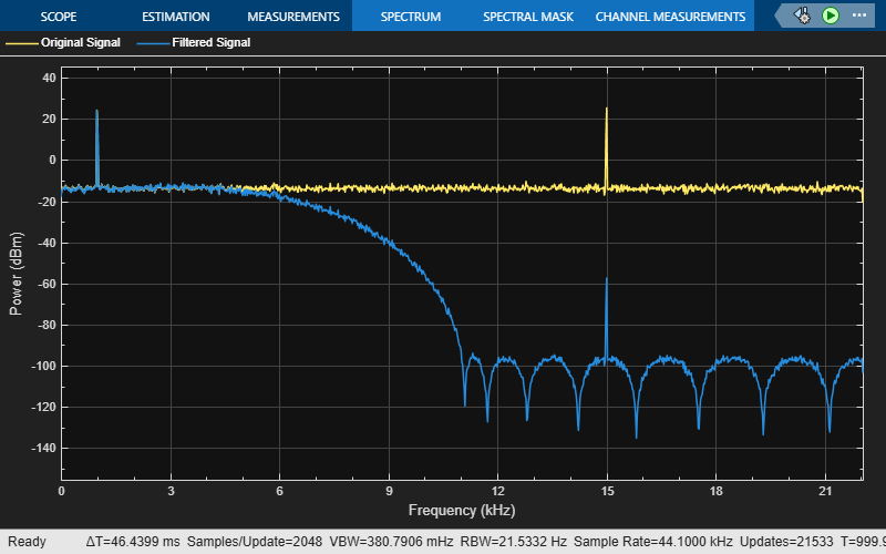
Open the designLowpassfilter.slx model. The input signal in the model is a sum of two sine waves with the frequencies of 1 kHz and 15 kHz. The Random Source block adds zero-mean white Gaussian noise with a variance of 0.05 to the sum of sine waves. The Digital Filter Design block filters the input signal. View the spectra of the original signal and the filtered signal in the spectrum analyzer.
Double-click the Digital Filter Design block. The block opens the Filter Designer app with these settings:
Lowpass FIR selected as the filter response
Frequency units set to
NormalizedRate specification set to
Single-rateOrder mode set to
MinimumPassband frequency set to 0.2
Stopband frequency set to 0.5
You can change any of the design parameters, click Update Filter in the app toolstrip, and view the updated filter response in the app.
With these design parameters, the Digital Filter Design block represents a lowpass FIR filter with a Direct-Form FIR structure. The filter passes all frequencies up to 20% of the Nyquist frequency (half the sample rate), and stops frequencies greater than or equal to 50% of the Nyquist frequency as defined by the Passband frequency and Stopband frequency parameters.
Run Model
The Digital Filter Design block acts as a lowpass FIR filter. Visualize the spectra of the noisy input signal and the filtered output signal in the spectrum analyzer. The lowpass FIR filter passes the 1 kHz frequency and attenuates the 15 kHz frequency.
open_system("designLowpassfilter.slx")
sim("designLowpassfilter.slx")
Use the Digital Filter Design block to create a highpass FIR filter in Simulink®. Use the same model as in the Design Lowpass FIR Filter Using Digital Filter Design Block example as a starting point.
Design Filter
First, design the highpass FIR filter.
Double-click the Digital Filter Design block in the designLowpassfilter.slx model and change these settings in the Filter Designer app:
Select the Highpass FIR filter response.
Set Stopband frequency to 0.2.
Set Passband frequency to 0.5.
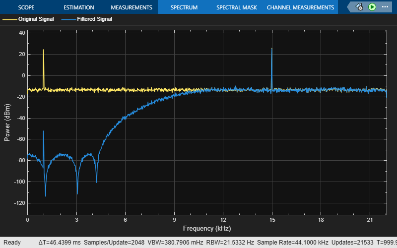
Click Update Filter to design the highpass FIR filter. The Digital Filter Design block now represents a highpass FIR filter with a direct-form FIR structure. The filter passes all frequencies greater than or equal to 50% of the Nyquist frequency (half the sample rate), and stops frequencies less than or equal to 20% of the Nyquist frequency as defined by the Stopband frequency and Passband frequency parameters.
Alternatively, you can open the equivalent designHighpassfilter.slx model.
Run Model
Next, run the model. Visualize the spectra of the noisy sinusoidal input signal and the filtered output signal in the spectrum analyzer.
The highpass FIR filter passes the 15 kHz frequency and attenuates the 1 kHz frequency.
open_system("designHighpassfilter")
sim("designHighpassfilter.slx")
Create high-frequency noise using the Digital Filter Design-Highpass FIR Filter block that you design in the Design Highpass FIR Filter Using Digital Filter Design Block example. Filter out this noise from the input signal using the Digital Filter Design-Lowpass FIR Filter block that you design in the Design Lowpass FIR Filter Using Digital Filter Design Block example.
Open the filterHighFrequencyNoise.slx model.
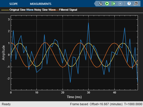
The input to the model is a noisy sinusoidal signal with high-frequency noise. To generate the high-frequency noise, pass a uniform random signal to the Digital Filter Design-Highpass FIR Filter block. Add the generated noise to the input sinusoidal signal of frequency 75 Hz.
Pass the noisy sine wave to the Digital Filter Design-Lowpass FIR Filter block. The lowpass FIR filter removes the high-frequency noise from the input signal. View the original sinusoidal signal, the noisy sinusoidal signal, and the filtered output in the time scope. Set the Time span parameter in the Time Scope block to One frame period.
open_system("filterHighFrequencyNoise")
sim("filterHighFrequencyNoise.slx")
Ports
Input
Output
Parameters
Designer Tab

For more information about the design parameters in the app, see Filter Designer.
You can tune the filter specifications in the Filter Designer app during simulation if your changes do not modify the filter length or the filter order. As you apply the changes, the Digital Filter Design block updates to reflect the new filter configuration.
Block Characteristics
Data Types |
|
Direct Feedthrough |
|
Multidimensional Signals |
|
Variable-Size Signals |
|
Zero-Crossing Detection |
|