Open-Loop Control of 3-Phase AC Motors Using STM32 Processor Based Boards
This example uses open-loop control (also known as scalar control or Volts/Hz control) to run a motor. This technique varies the stator voltage and frequency to control the rotor speed without using any feedback from the motor. You can use this technique to check the integrity of the hardware connections. A constant speed application of open-loop control uses a fixed-frequency motor power supply. An adjustable speed application of open-loop control needs a variable-frequency power supply to control the rotor speed. To ensure a constant stator magnetic flux, keep the supply voltage amplitude proportional to its frequency.
Open-loop motor control does not have the ability to consider the external conditions that can affect the motor speed. Therefore, the control system cannot automatically correct the deviation between the desired and the actual motor speed.
The model in this example runs the motor by using an open-loop motor control algorithm. The model helps you get started with the Motor Control Blockset™ and verify the hardware setup by running the motor. The target model algorithm also reads the ADC values from the current sensors and sends the values to the host model by using serial communication.
You can use this model to:
Check the connection to the target.
Verify the hardware and software environment.
Check ADC offsets for current sensors.
Run a new motor with an inverter, processors and its required peripherals setup for the first time
Prerequisites
Complete the following tutorials:
Required Hardware
Hardware Connection

Jumper Connection
Configure the following connections on X-NUCLEO-IHM07M1 board to perform FOC to the control BLY172S-24V-4000 motor.

Available Models
You can use the mcb_open_loop_control_nucleo_f401re or mcb_open_loop_control_nucleo_g474re models with the X-NUCLEO-IHM07M1 expansion board for both simulation and code generation.
Open the mcb_open_loop_control_nucleo_f401re model.
A pre-configured model is included for your convenience.
Peripheral Configurations
STM32CubeMX Configurations
ADC configuration
The ADC and PWM synchronization occurs such that ADC injected group conversions start based on Timer 1 update events.
The ADC channel is configured to read current feedback from the injected group conversions of ADC 1 and the reference speed from regular group conversions.

PWM Configuration
PWM frequency and PWM channels are configured. The
Timer1is configured to generate update events to synchronize the ADC with the PWM. This synchronization is important to read current feedback at right time.The repetition counter is set to 1 to ensure update events occur once every period.

Peripheral Block Configurations
Double-click the blocks to open the block parameter configurations. Ensure the specified parameter values are the same if you want to run this example on a different hardware board.
Configure Analog to Digital Converter block
The algorithm in this example uses asynchronous scheduling. The pulse width modulation (PWM) block triggers the ADC conversion. At the end of the conversion, the ADC posts an interrupt that triggers the open-loop algorithm.


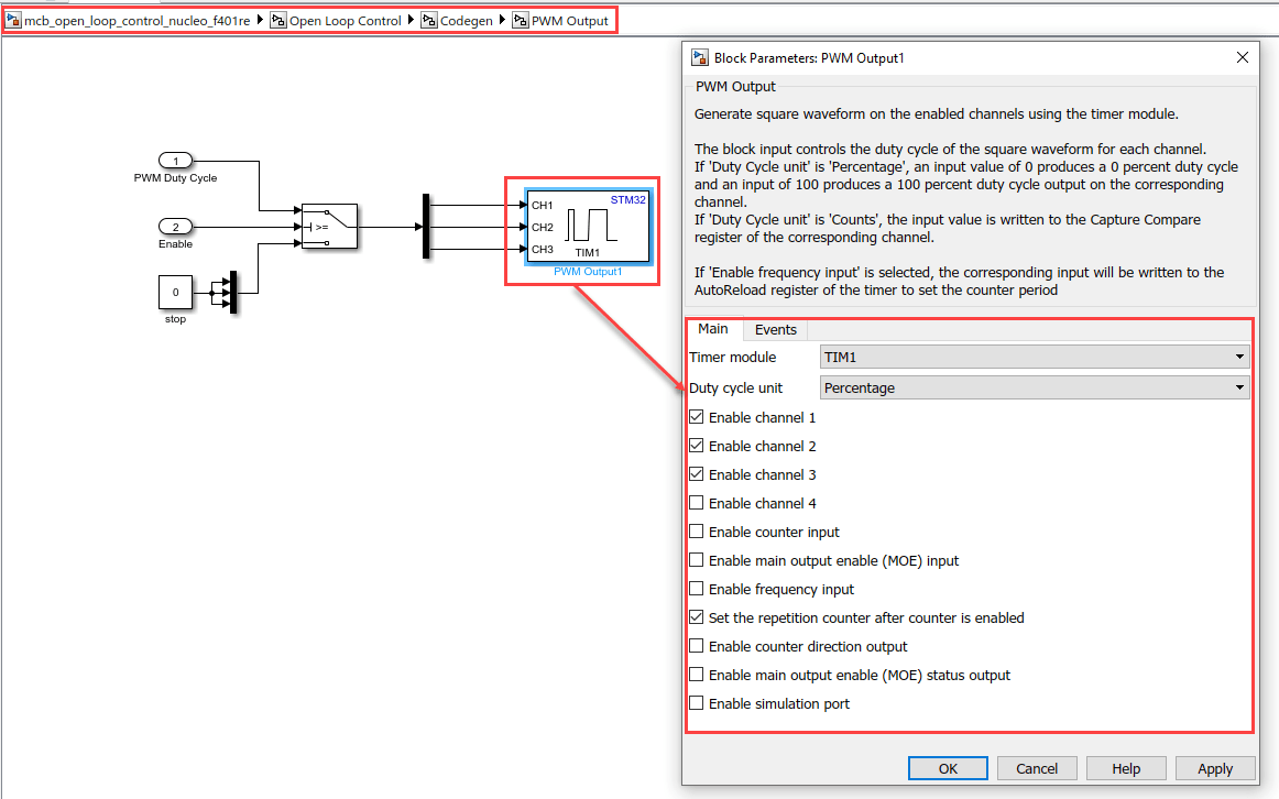
Configure PWM Output block
Select the Set the repetition counter after counter is enabled parameter to update the event when the timer counter overflows.

Simulate Model
This example supports simulation. Follow these steps to simulate the model.
1. Open the model included with this example.
2. Click Run on the Simulation tab to simulate the model.
3. Click Data Inspector on the Simulation tab to view and analyze the simulation results. To verify the signals, start the motor by clicking the Push Button available in the model during simulation.
Generate Code, Deploy and Run on Target Hardware
This section shows you to generate code and run the motor by using open-loop control.
NOTE: Some PMSMs do not run at higher speeds, especially when the shaft is loaded. To resolve this issue, you should apply more voltages corresponding to a given frequency. You can use these steps to increase the applied voltages in the model:
1. Navigate to this path in the model: /Open Loop Control/Control_System/VabcCalc/.
2. Update the gain Correction_Factor_sinePWM as 20%.
3. For safety reasons, regularly monitor the motor shaft, motor current, and motor temperature.
Generate Code and Run Model to Implement Open-Loop Control
1. Simulate the target model and observe the simulation results.
2. Complete the hardware connections.
3. Update these motor parameters in the Configuration panel of the target model.
Number of Pole Pairs
PWM Frequency [Hz]
Base Speed [RPM]
Data type for control algorithm
4. In the Hardware tab, click Monitor & Tune. You can observe from the Diagnostic Viewer that the model code is being generated and the host connects to the target after loading the generated executable. View the Simulink Data Inspector.

5. To spin the motor, click the Push Button (blue push button) on the hardware board.
6. After the motor starts running, observe the ADC counts for the  and
and  currents in the Simulink Data Inspector.
NOTE: This example may not allow the motor to run at full capacity. Begin running the motor at a low speed. In addition, it is recommended to change the Reference Speed in small steps (for example, for a motor with a base speed of 3000 rpm, start running the motor at 500 rpm and then increase or decrease the speed in multiples of 200 rpm).
If the motor does not run, press the Blue push button to stop the motor, and change the Speed in RPM Constant block to external mode in the model. Then press the Blue push button to start the motor and run it again.
Generate Code and Run Model to Calibrate ADC Offset
When the motor is idle, observe the  and
and  in Simulink Data Inspector. The flat line in the Data Inspector is considered as an ADC offset.
Other Things to Try
Try running the example model on an SOC blockset and analyze the results.
Try running the example using mcb_open_loop_control_nucleo_g474re model on|STM32G4xx Based| hardware board.