Generate HDL Code for Simscape Models with Multiple Networks
This example shows how you can run the Simscape HDL Workflow Advisor to generate the HDL implementation model for a Simscape™ model that contains multiple networks. You can also generate a validation logic that numerically compares each Simscape network with the corresponding state-space implementation in the HDL implementation model. The Simscape model in this example is a solar power inverter partitioned into two networks. To learn how this network is partitioned, see Partition Simscape Models Containing a Large Network into Multiple Smaller Networks.
Why Use a Simscape Model with Multiple Networks
When your Simscape model contains many switching elements, the state-space representation can contain a large number of modes. The generated HDL implementation model for such a large design can consume a significantly large number of resources, and may even fail to synthesize on the target FPGA device. To reduce the number of modes, you can partition the Simscape network in your model into multiple networks, and then run the Simscape HDL Workflow Advisor.
Solar Power Inverter Model with Multiple Networks
To open the model that contains multiple networks, run:
open_system('sschdlexSolarInverterPartitionedNetworkExample')

The model consists of four parts: solar panel, boost controller, inverter controller, and a boost converter and full bridge inverter. The solar panel is modeled in Simulink® by using lookup tables. The boost controller and inverter controller provide the control signals for the boost converter and the full bridge inverter which is an H-bridge.
The original model contains the boost converter and full bridge inverter as a single network inside one subsystem. To see this model, enter:
open_system('sschdlexSolarInverterSingleNetworkExample')
The partitioned model contains the two networks inside a single subsystem. To see the partitioned network, open the Network subsystem.
open_system('sschdlexSolarInverterPartitionedNetworkExample/Network')

Run Simscape HDL Workflow Advisor for Model with Multiple Networks
1. To open the Simscape HDL Workflow Advisor for the model, enter:
sschdladvisor('sschdlexSolarInverterPartitionedNetworkExample')
2. Run the workflow to the Check model compatibility task.
The Simscape HDL Workflow Advisor lists the number of networks present in the model and the number of algebraic and differential variables for each network. The Advisor uses the Solver Configuration block to identify each unique network in your model.
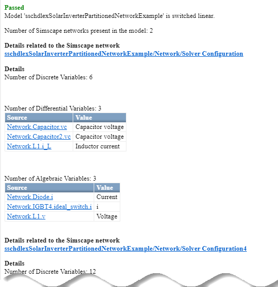
3. Run the Extract discrete equations task.
This task displays Simulation stop time, Number of solver iterations, number of states, inputs, outputs, modes, differential variables, and state-space representation for each Simscape network.
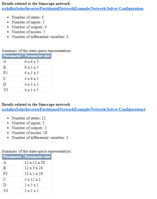
The state-space representation now uses fewer modes. The number of modes is 28 for the boost converter and 5 for the full bridge inverter, which results in a total number of 33 modes. The reduction in the number of modes saves area of the HDL implementation model on the target device.
Generate HDL Implementation Model and View Resource Consumption
1. Run the Generate implementation model task. After the task passes, you see a link to the HDL implementation model gmStateSpaceHDL_sschdlexSolarInverterPartit. Click the link to open the HDL implementation model or enter:
open_system('gmStateSpaceHDL_sschdlexSolarInverterPartit')
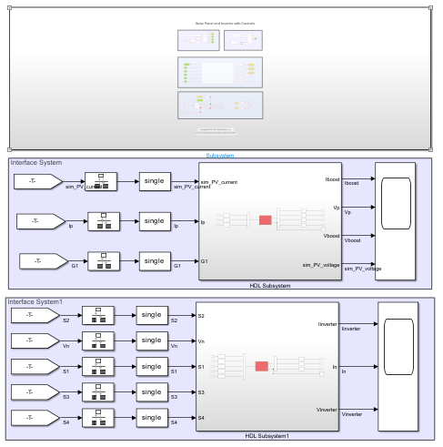
The model contains two HDL Subsystems. The HDL Subsystem block models the state-space equations for the boost converter. The HDL Subsystem1 block models the state-space equations for the full bridge inverter.
2. Enable generation of the resource utilization report.
hdlset_param('gmStateSpaceHDL_sschdlexSolarInverterPartit', 'ResourceReport', 'on')
3. Run the makehdl function to generate code. To generate HDL code for both HDL Subsystem blocks, you can place HDL Subsystem and HDL Subsystem1 blocks inside another top level subsystem and name this subsystem as HDL_DUT. Then generate HDL code.
makehdl('gmStateSpaceHDL_sschdlexSolarInverterPartit/HDL_DUT')
4. As you generate HDL code, open the Code Generation Report. The resource utilization report indicates the amount of adders, multipliers, and registers that might be consumed on the target FPGA device.
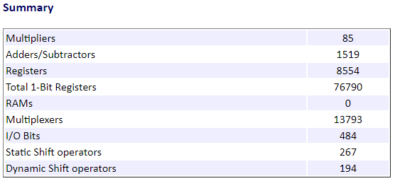
The overall resource consumption of the two networks is significantly less than the resource consumption of a single, large network. To learn about the resource consumption of the single solar power inverter network, see Partition Simscape Models Containing a Large Network into Multiple Smaller Networks.