Create a MATLAB Testbench
The HDL Verifier™ software provides a means for verifying HDL modules within the MATLAB® environment. You do so by coding an HDL model and a MATLAB function that can share data with the HDL model. This chapter discusses the programming, interfacing, and scheduling conventions for MATLAB testbench functions that communicate with the HDL simulator. Note that cosimulation with Vivado® simulator does not support MATLAB function cosimulation.
MATLAB testbench functions let you verify the performance of the HDL model, or of components within the model. A testbench function drives values onto signals connected to input ports of an HDL design under test and receives signal values from the output ports of the module.
The following figure shows how a MATLAB function wraps around and communicates with the HDL simulator during a testbench simulation session.

When linked with MATLAB, the HDL simulator functions as the client, with MATLAB as the server. The following figure shows a multiple-client scenario connecting to the server at TCP/IP socket port 4449.
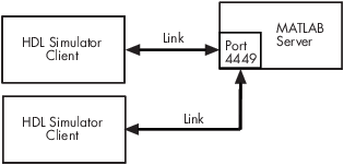
The MATLAB server can service multiple simultaneous HDL simulator sessions and HDL
modules. However, you should follow recommended guidelines to help the server track the
I/O associated with each module and session. The MATLAB server, which you start with the supplied function hdldaemon, waits for connection requests from instances of the HDL
simulator running on the same or different computers. When the server receives a
request, it executes the specified MATLAB function you have coded to perform tasks on behalf of a module in your HDL
design. Parameters that you specify when you start the server indicate whether the
server establishes shared memory or TCP/IP socket communication links.
Refer to Cosimulation Configurations for valid machine configurations.
Note
The programming, interfacing, and scheduling conventions for testbench functions and component functions are virtually identical. For the most part, the same procedures apply to both types of functions.
Follow these workflow steps to create a MATLAB testbench session for cosimulation with the HDL simulator.
Set breakpoints for interactive HDL debug (optional).
Write HDL Modules for MATLAB Testbench
Specify Port Direction Modes in HDL Module for Use with Testbench
Specify Port Data Types in HDL Modules for Use with Testbench
Coding HDL Modules for Verification with MATLAB
The most basic element of communication in the HDL Verifier interface is the HDL module. The interface passes all data between the HDL simulator and MATLAB as port data. The HDL Verifier software works with any existing HDL module. However, when you code an HDL module that is targeted for MATLAB verification, you should consider its name, the types of data to be shared between the two environments, and the direction modes.
Choose HDL Module Name for Use with MATLAB Testbench
Although not required, when naming the HDL module, consider choosing a name that also can be used as a MATLAB function name. (Generally, naming rules for VHDL® or Verilog® and MATLAB are compatible.) By default, HDL Verifier software assumes that an HDL module and its simulation function share the same name. See Bind Testbench Function Calls With matlabtb.
For details on MATLAB function-naming guidelines, see “MATLAB Programming Tips” on files and file names in the MATLAB documentation.
Specify Port Direction Modes in HDL Module for Use with Testbench
In your module statement, you must specify each port with a direction mode (input, output, or bidirectional). The following table defines these three modes.
| Use VHDL Mode... | Use Verilog Mode... | For Ports That... |
|---|---|---|
IN | input | Represent signals that can be driven by a MATLAB function or Simulink® testbench |
OUT | output | Represent signal values that are passed to a MATLAB function or Simulink testbench |
INOUT | inout | Represent bidirectional signals that can be driven by or pass values to a MATLAB function or Simulink testbench |
Specify Port Data Types in HDL Modules for Use with Testbench
This section describes how to specify data types compatible with MATLAB for ports in your HDL modules. For details on how the HDL Verifier interface converts data types for the MATLAB environment, see Supported Data Types.
Note
If you use unsupported types, the HDL Verifier software issues a warning and ignores the port at run time. For example, if you define your interface with five ports, one of which is a VHDL access port, at run time, then the interface displays a warning and your code sees only four ports.
Port Data Types for VHDL Entities. In your entity statement, you must define each port that you plan to test with MATLAB with a VHDL data type that is supported by the HDL Verifier software. The interface can convert scalar and array data of the following VHDL types to comparable MATLAB types:
STD_LOGIC,STD_ULOGIC,BIT,STD_LOGIC_VECTOR,STD_ULOGIC_VECTOR, andBIT_VECTORINTEGERandNATURALREALTIMEEnumerated types, including user-defined enumerated types and
CHARACTER
The interface also supports all subtypes and arrays of the preceding types.
Note
The HDL Verifier software does not support VHDL extended identifiers for the following components:
Port and signal names used in cosimulation
Enum literals when used as array indices of port and signal names used in cosimulation
However, the software does support basic identifiers for VHDL.
Port Data Types for Verilog Modules. In your module definition, you must define each port that you plan to test with MATLAB with a Verilog port data type that is supported by the HDL Verifier software. The interface can convert data of the following Verilog port types to comparable MATLAB types:
reg
integer
wire
Note
HDL Verifier software does not support Verilog escaped identifiers for port and signal names used in cosimulation. However, it does support simple identifiers for Verilog.
Compile and Elaborate HDL Design for Use with Testbench
After you create or edit your HDL source files, use the HDL simulator compiler to compile and debug the code.
For more examples, see the HDL Verifier tutorials and demos. For details on using the HDL compiler, see the simulator documentation.
Sample VHDL Entity Definition
This sample VHDL code fragment defines the entity decoder. By
default, the entity is associated with MATLAB testbench function decoder.
The keyword PORT marks the start of the entity's port
clause, which defines two IN
ports—isum and qsum—and
three OUT ports—adj,
dvalid, and odata. The output ports
drive signals to MATLAB function input ports for processing. The input ports receive
signals from the MATLAB function output ports.
Both input ports are defined as vectors consisting of five standard logic
values. The output port adj is also defined as a standard
logic vector, but consists of only two values. The output ports
dvalid and odata are defined as scalar
standard logic ports. For information on how the HDL Verifier interface converts data of standard logic scalar and array types
for use in the MATLAB environment, see Supported Data Types.
ENTITY decoder IS
PORT (
  isum   : IN std_logic_vector(4 DOWNTO 0);
  qsum   : IN std_logic_vector(4 DOWNTO 0);
  adj    : OUT std_logic_vector(1 DOWNTO 0);
  dvalid : OUT std_logic;
  odata  : OUT std_logic);
END decoder ;
Write a Testbench Function
Coding MATLAB Cosimulation Functions
Coding a MATLAB function to verify an HDL module or component requires that you follow specific coding conventions. You must also understand the data type conversions that occur, and program data type conversions for operating on data and returning data to the HDL simulator.
To code a MATLAB function to verify an HDL module or component, perform the following steps:
Learn the syntax for a MATLAB HDL Verifier testbench function. See Syntax of a Testbench Function.
Understand how HDL Verifier software converts data from the HDL simulator for use in the MATLAB environment. See Supported Data Types.
Choose a name for the MATLAB function. See Bind HDL Module Component to MATLAB Testbench Function.
Define expected parameters in the function definition line. See MATLAB Function Syntax and Function Argument Definitions.
Determine the types of port data being passed into the function. See MATLAB Function Syntax and Function Argument Definitions.
Extract and, if applicable to the simulation, apply information received in the
portinfostructure. See Gaining Access to and Applying Port Information.Convert data for manipulation in the MATLAB environment, as applicable. See Converting HDL Data to Send to MATLAB or Simulink.
Convert data that needs to be returned to the HDL simulator. See Converting Data for Return to the HDL Simulator.
For more tips, see Testbench and Component Function Writing.
Syntax of a Testbench Function
The syntax of a MATLAB testbench function is
function [iport, tnext] = MyFunctionName(oport, tnow, portinfo)
See the MATLAB Function Syntax and Function Argument Definitions for an explanation of each of the function arguments.
Sample MATLAB Testbench Function
This section uses a sample MATLAB function to identify sections of a MATLAB testbench function required by the HDL Verifier software. You can see the full text of the code used in this sample in the section MATLAB Builder EX Function Example: manchester_decoder.m.
As the first step to coding a MATLAB
Builder™ EX testbench function, you must understand how the data modeled in
the VHDL entity maps to data in the MATLAB
Builder EX environment. The VHDL entity decoder is defined as follows:
ENTITY decoder IS
PORT (
  isum   : IN std_logic_vector(4 DOWNTO 0);
  qsum   : IN std_logic_vector(4 DOWNTO 0);
  adj    : OUT std_logic_vector(1 DOWNTO 0);
  dvalid : OUT std_logic;
  odata  : OUT std_logic
  );
END decoder ;
The following discussion highlights key lines of code in the definition of the
manchester_decoder
MATLAB
Builder EX function:
Specify the MATLAB function name and required parameters.
The following code is the function declaration of the
manchester_decoderMATLAB Builder EX function.function [iport,tnext] = manchester_decoder(oport,tnow,portinfo)
See MATLAB Function Syntax and Function Argument Definitions.
The function declaration performs the following actions:
Names the function. This declaration names the function
manchester_decoder, which differs from the entity namedecoder. Because the names differ, the function name must be specified explicitly later when the entity is initialized for verification with thematlabtbormatlabtbevalfunction. See Bind HDL Module Component to MATLAB Testbench Function.Defines required argument and return parameters. A MATLAB Builder EX testbench function must return two parameters,
iportandtnext, and pass three arguments,oport,tnow, andportinfo, and must appear in the order shown. See MATLAB Function Syntax and Function Argument Definitions.The function outputs must be initialized to empty values, as in the following code example:
tnext = [];
iport = struct();
You should initialize the function outputs at the beginning of the function, to follow recommended best practice.
The following figure shows the relationship between the entity's ports and the MATLAB Builder EX function's
iportandoportparameters.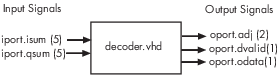
For more information on the required MATLAB Builder EX testbench function parameters, see MATLAB Function Syntax and Function Argument Definitions.
Make note of the data types of ports defined for the entity being simulated.
The HDL Verifier software converts HDL data types to comparable MATLAB Builder EX data types and vice versa. As you develop your MATLAB Builder EX function, you must know the types of the data that it receives from the HDL simulator and needs to return to the HDL simulator.
The VHDL entity defined for this example consists of the following ports
VHDL Example Port Definitions
Port Direction Type... Converts to/Requires Conversion to... isumINSTD_LOGIC_VECTOR(4 DOWNTO 0)A 5-bit column or row vector of characters where each bit maps to a standard logic character literal. qsumINSTD_LOGIC_VECTOR(4 DOWNTO 0)A 5-bit column or row vector of characters where each bit maps to a standard logic character literal. adjOUTSTD_LOGIC_VECTOR(1 DOWNTO 0)A 2-element column vector of characters. Each character matches a corresponding character literal that represents a logic state and maps to a single bit. dvalidOUTSTD_LOGICA character that matches the character literal representing the logic state. odataOUTSTD_LOGICA character that matches the character literal representing the logic state. For more information on interface data type conversions, see Supported Data Types.
Set up any required timing parameters.
The
tnextassignment statement sets up timing parametertnextsuch that the simulator calls back the MATLAB Builder EX function every nanosecond.tnext = tnow+1e-9;
Convert output port data to MATLAB data types for processing.
The following code excerpt illustrates data type conversion of output port data.
%% Compute one row and plot
isum = isum + 1;
adj(isum) = mvl2dec(oport.adj');
data(isum) = mvl2dec([oport.dvalid oport.odata]);
.
.
.
The two calls to
mvl2decconvert the binary data that the MATLAB Builder EX function receives from the entity's output ports,adj,dvalid, andodatato unsigned decimal values that MATLAB Builder EX can compute. The function converts the 2-bit transposed vectoroport.adjto a decimal value in the range 0 to 4 andoport.dvalidandoport.odatato the decimal value 0 or 1.MATLAB Function Syntax and Function Argument Definitions provides a summary of the types of data conversions to consider when coding simulation MATLAB functions.
Convert data to be returned to the HDL simulator.
The following code excerpt illustrates data type conversion of data to be returned to the HDL simulator.
 if isum == 17
   iport.isum = dec2mvl(isum,5);
   iport.qsum = dec2mvl(qsum,5);
else
   iport.isum = dec2mvl(isum,5);
end
The three calls to
dec2mvlconvert the decimal values computed by MATLAB Builder EX to binary data that the MATLAB Builder EX function can deposit to the entity's input ports,isumandqsum. In each case, the function converts a decimal value to 5-element bit vector with each bit representing a character that maps to a character literal representing a logic state.Converting Data for Return to the HDL Simulator provides a summary of the types of data conversions to consider when returning data to the HDL simulator.
MATLAB Builder EX Function Example: manchester_decoder.m
function [iport,tnext] = manchester_decoder(oport,tnow,portinfo)
% MANCHESTER_DECODER  Test bench for VHDL 'decoder'
%  [IPORT,TNEXT]=MANCHESTER_DECODER(OPORT,TNOW,PORTINFO) -
%    Implements a test of the VHDL decoder entity which is part
%    of the Manchester receiver demo.  This test bench plots
%    the IQ mapping produced by the decoder.
%
%      iport              oport
%            +-----------+
% isum -(5)->|           |-(2)-> adj
% qsum -(5)->| decoder   |-(1)-> dvalid
%            |           |-(1)-> odata
%            +-----------+
%
%   isum - Inphase Convolution value
%   qsum - Quadrature Convolution value
%   adj  - Clock adjustment ('01','00','10')
%   dvalid - Data validity ('1' = data is valid)
%   odata - Recovered data stream
%
% Adjust = 0 (00b), generate full 16 cycle waveform

%   Copyright 2003-2009 The MathWorks, Inc.

persistent isum;
persistent qsum;
%persistent ga;
persistent x;
persistent y;
persistent adj;
persistent data;
global testisdone;
% This useful feature allows you to manually
% reset the plot by simply typing: >manchester_decoder
tnext = [];
iport = struct();

if nargin == 0,
    isum = [];
    return;
end

if exist('portinfo') == 1
    isum = [];
end

tnext = tnow+1e-9;
if isempty(isum),  %% First call
    scale = 9;
    isum = 0;
    qsum = 0;
    for k=1:2,
        ga(k) = subplot(2,1,k);
        axis([-1 17 -1 17]);
        ylabel('Quadrature');
        line([0 16],[8 8],'Color','r','LineStyle',':','LineWidth',1)
        line([8 8],[0 16],'Color','r','LineStyle',':','LineWidth',1)
    end
    xlabel('Inphase');
    subplot(2,1,1);
    title('Clock Adjustment (adj)');
    subplot(2,1,2);
    title('Data with Validity');
    iport.isum = '00000';
    iport.qsum = '00000';
    return;
end

% compute one row, then plot
isum = isum + 1;
adj(isum) = bin2dec(oport.adj');
data(isum) = bin2dec([oport.dvalid oport.odata]);

if isum == 17,
    subplot(2,1,1);
    for k=0:16,
        if adj(k+1) == 0,  % Bang on!
            line(k,qsum,'color','k','Marker','o');
        elseif adj(k+1) == 1,  %
            line(k,qsum,'color','r','Marker','<');
        else
            line(k,qsum,'color','b','Marker','>');
        end
    end
    subplot(2,1,2);
    for k=0:16,
        if data(k+1) < 2,  % Invalid
            line(k,qsum,'color','r','Marker','X');
        else
            if data(k+1) == 2,  %Valid and 0!
                line(k,qsum,'color','g','Marker','o');
            else
                line(k,qsum,'color','k','Marker','.');
            end
        end
    end

    isum = 0;
    qsum = qsum + 1;
    if qsum == 17,
        qsum = 0;
        disp('done');
        tnext = [];  % suspend callbacks
        testisdone = 1;
        return;
    end
    iport.isum = dec2bin(isum,5);
    iport.qsum = dec2bin(qsum,5);
else
    iport.isum = dec2bin(isum,5);
end