Relating HDL Clocks and Resets with Simulink Sample Times
This example illustrates the relationship of Simulink® sample times to HDL clocks and resets. The example uses HDL Verifier™ to cosimulate a synchronous Verilog parity check module. The example also contains the following:
Explains how delta-time iterations in the HDL simulator (ModelSim® or Xcelium™) may affect cosimulation results
Shows the use of the Clocks pane in the HDL Cosimulation block to drive clock signals in HDL
Shows how you can accurately compare cosimulation results by taking the HDL reset logic delays into consideration
Verilog Code Used for Cosimulation
Parity checking is a method of adding a parity bit to a data stream in order to check that data for any errors. In this example we will use an "even parity bit" scheme. The HDL module is designed to be synchronous and updates its state on every rising edge of clock.
The synchronous Parity Checker module (paritychecker_clk_dut.v) accepts an 8-bit input, outputs 1 even-parity bit, and is driven on every rising clock edge.
Effects of Changing Simulink Sample Times in a Cosimulation
If you are using ModelSim or QuestaSim, the model parity_check_clk.slx should be open. If you are using Xcelium, close the ModelSim model and open the model parity_check_clk_in.slx.
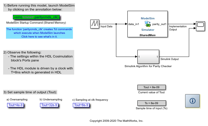
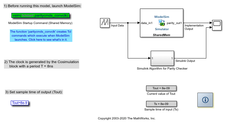
In the model we use an 8-bit counter to provide input data to the HDL code through the HDL Cosimulation block, and its equivalent Simulink algorithm. A scope is used to view their outputs and compare results. The model showcases how the Simulink sampling rate affects cosimulation with an HDL module. The clickable annotations can be used to change the sample time of the HDL Cosimulation block's output port (Tout).
Note that the clock and reset inputs for the design under test are generated within the HDL driver module, (paritychecker_clk_driver.v). Reset is held high for the first 16ns and is low thereafter. The clock has a period of 8ns, and is set up such that its first rising edge occurs at 4ns. Hence the module is capable of updating its output at a maximum rate of 8ns, that is, at every rising edge of clock.
1. Launch ModelSim or Xcelium
Before running the model, you must first launch the HDL simulator. Use the startup command provided within the model for this.
2. Observe the settings within the HDL Cosimulation block's Ports pane
Double-click on the HDL Cosimulation block to edit the cosimulation parameters. The Block Parameters dialog appears. Select the Ports tab.
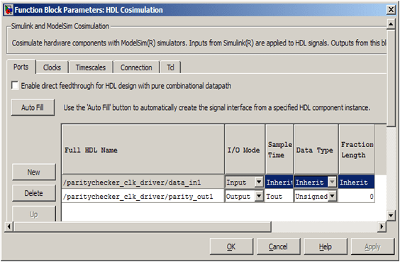
The sample time of the output port (
parity_out1) is set to Tout. There are numerous ways to specify the value of Tout. We have set the initial value of Ts from within the model'sPreLoadFcncallback (see Create Model Callbacks (Simulink)). We set new values for Tout using either of the clickable annotations provided in the model. You can set the value of Tout at the MATLAB® Command prompt as well.
Note that the option for allowing direct feedthrough has not been checked - this is because our Verilog code is not purely combinational.
The model provides three clickable annotations for setting the sampling time of the output ports of the HDL Cosimulation block) Tout = 32ns, 8ns, and 4ns.
3. Run the model with all three versions of Tout
Tout = 32ns
Output of HDL module is sampled by Simulink at every 32ns
The sampling rate of the output port is lower than the clock rate, Tout = 4x(HDL clock period)
The output of the HDL Cosimulation block is Undersampled, as a result of which and the
parity_out1signal within the HDL simulator does not match up with the Simulink scope result
Tout = 8ns
Output of HDL module is sampled by Simulink at every 8ns
The sampling rate of the output port perfectly matches the clock rate, Tout = (HDL clock period)
None of the outputs are missed, and the comparison waveforms match up
Tout = 4ns
Output of HDL module is sampled by Simulink at every 2ns
The sampling rate of the is higher than the clock rate, Ts = 0.5x(HDL clock period)
The output is Oversampled and the higher output sampling rate does not pay any dividend here
Hence understanding the clocking rate of a synchronous HDL module can be advantageous for cosimulation if you do not want to oversample or undersample the output from HDL.
4. Observe results in the Simulink Scope when Tout = 8ns
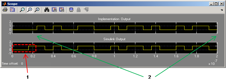
You will notice that the outputs from the Simulink algorithm match the outputs obtained from the HDL Cosimulation block (labeled as 2 in the image), except for the first 24ns (labeled as 1 in the image). The initial values of the two outputs do not match up due to the reset logic used within HDL (which Simulink does not know about and does not incorporate in its algorithm). We will discuss this in detail later in the example.
Effect of Clocks Driving an HDL Module and Race Conditions
It is important to understand that the Simulink engine does not work in delta-time cycles and hence Simulink queries the output port of the HDL Cosimulation block at definite discrete time intervals. On the other hand, the HDL simulator does not make any guarantees as to the order of a value change versus some other blocking signal assignment. Thus, if the Simulink values are driven/ sampled at the same time as an active clock edge in the HDL, there is a race condition. In order to avoid such race conditions it is essential that Simulink values are not driven/ sampled at the same time as an active clock edge in HDL.
In the Verilog code paritychecker_clk_driver.v note how the positive edge of the clock (which is the active edge) has purposely been offset by half its period so as avoid a potential race condition.
Case for 24ns delay
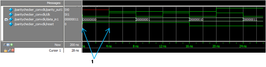
The Verilog code is driven such that the module is reset for the first 16ns. However, the output mismatch seen on the Simulink scope is for 24ns. In order to better understand why this delay occurs, we have captured a snapshot of the HDL simulator waveform (with delta-time delays and events expanded), when the simulation was run with Tout=8ns:
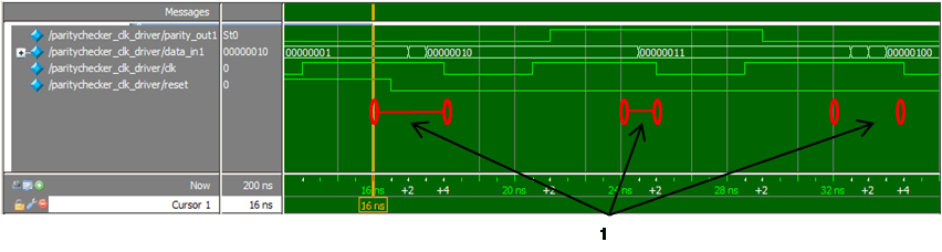
At 16ns, the output parity_out1 within the HDL simulator still holds its previous state, since the output is only slated to change at rising edge of clock. Hence Simulink samples the previous state of output at 16ns. Also note, that even though we have set Ts=Tout=8ns in Simulink, the Simulink engine does not know how the HDL simulator will perform its delta-time iterations. Hence the outputs could be sampled by Simulink within the delta-time ranges (labeled 1) shown in the image above.
Convenience Clock
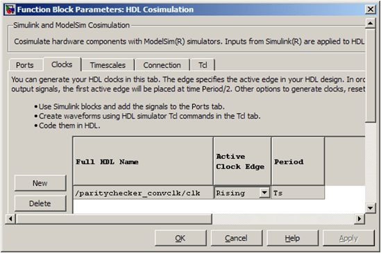
Instead of creating your own driver code (testbench) for the HDL module, you can use the HDL Cosimulation block's convenience clock to generate the clocking input. You can specify the clock period (T) and its active edge in the Clocks pane of the HDL Cosimulation block. This clock generated by the HDL Cosimulation block has a deliberate T/2 delay applied to the first active clock edge (which you specify) - in order to avoid race conditions. In order to show how to use this clock, we have provided models, parity_check_convclk.slx (ModelSim) and parity_check_convclk_in.slx (Xcelium) which use a clock created by the HDL Cosimulation block as the driving signal for the modified version of the even parity checker modules (paritychecker_convclk.v).
The Clocks pane of the HDL Cosimulation blocks is set as shown in the image below. Notice how the active edge of clock is set to be rising:
Run the model and observe outputs
The results are the same as those obtained in the example Timescales: Absolute, Relative and Automatic. The output of the HDL simulator waveform is captured in the image below:
Notice how an initial phase shift of T/2 is applied to the first active edge of clk - shown by the label 1 in the image.
Accounting for Reset Delay in Order to Compare Cosimulation Results
Simulink does not know about any resetting logic that the HDL module may have in place and does not incorporate such reset logic in its algorithm. Hence the HDL cosimulation results will be out of sync with respect to the Simulink algorithm (subsystem).
Now, if you need to compare the output of the HDL Cosimulation block with the results obtained from Simulink's algorithm, you have to ensure that both these simulations are synchronized. There are a number of ways to achieve this, one of which are shown in parity_check_reset.slx (ModelSim) and parity_check_reset_in.slx (Xcelium).
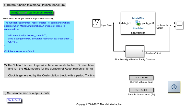
Here we use the tclstart arguments to run the HDL simulator for 16ns (reset period) immediately after HDL Verifier sets up the cosimulation link. Hence the HDL module runs for 16ns before you start the simulation in Simulink.
Run the model and observe Scope output

Key Points to Note:
All port sample times and clock specifications are in Simulink time. For example, if timescale is set to '1s in Simulink corresponds to 1s in HDL simulator', the clock period should be T=8ns. However, if the timescale is set to '1s in Simulink corresponds to 1ns in HDL simulator', the clock period should be T=8s. This is explained in the example Timescales: Absolute, Relative and Automatic
The clock generated in the clocks pane is meant to drive HDL code only
All signals driven from the Tcl pane or in the
tclstartof the HDL simulator's launch command are in HDL timeAll signals driven from within HDL code are in HDL time