Uplink Control Channel Format 2
The Physical Uplink Control Channel (PUCCH) Format 2 is a transmission channel used to carry information regarding channel status reports as well as Hybrid Automatic Repeat request (HARQ) acknowledgments.
Uplink Control Information on PUCCH Format 2
The UE uses PUCCH format 2 control information to relay an estimate of the channel properties to the base station in order to aid channel dependent scheduling. Channel status reports include channel quality indication (CQI), rank indication (RI), and precoder matrix indication (PMI).
CQI — represents the recommended modulation scheme and coding rate that should be used for the downlink transmission.
RI — provides information about the rank of the channel, which is used to determine the optimal number of layers that should be used for the downlink transmission (only used for spatial multiplexed systems).
PMI — provides information about which precoding matrix to use (only used in closed loop spatial multiplexing systems).
HARQ-ACK can also be transmitted with channel status information. Two forms of channel coding exist—one for the CQI alone and another for the combination of CQI with HARQ-ACK.
Channel Coding for UCI CQI Indication
The CQI codewords are coded using a (20,A) block code and are a linear combination of the 13 basis sequences denoted by Mi,n and defined by the following equation.
The values of the basis sequence, Mi,n, for a (20,A) block code are given in the following table.
| i | Mi,0 | Mi,1 | Mi,2 | Mi,3 | Mi,4 | Mi,5 | Mi,6 | Mi,7 | Mi,8 | Mi,9 | Mi,10 | Mi,11 | Mi,12 |
|---|---|---|---|---|---|---|---|---|---|---|---|---|---|
| 0 | 1 | 1 | 0 | 0 | 0 | 0 | 0 | 0 | 0 | 0 | 1 | 1 | 0 |
| 1 | 1 | 1 | 1 | 0 | 0 | 0 | 0 | 0 | 0 | 1 | 1 | 1 | 0 |
| 2 | 1 | 0 | 0 | 1 | 0 | 0 | 1 | 0 | 1 | 1 | 1 | 1 | 1 |
| 3 | 1 | 0 | 1 | 1 | 0 | 0 | 0 | 0 | 1 | 0 | 1 | 1 | 1 |
| 4 | 1 | 1 | 1 | 1 | 0 | 0 | 0 | 1 | 0 | 0 | 1 | 1 | 1 |
| 5 | 1 | 1 | 0 | 0 | 1 | 0 | 1 | 1 | 1 | 0 | 1 | 1 | 1 |
| 6 | 1 | 0 | 1 | 0 | 1 | 0 | 1 | 0 | 1 | 1 | 1 | 1 | 1 |
| 7 | 1 | 0 | 0 | 1 | 1 | 0 | 0 | 1 | 1 | 0 | 1 | 1 | 1 |
| 8 | 1 | 1 | 0 | 1 | 1 | 0 | 0 | 1 | 0 | 1 | 1 | 1 | 1 |
| 9 | 1 | 0 | 1 | 1 | 1 | 0 | 1 | 0 | 0 | 1 | 1 | 1 | 1 |
| 10 | 1 | 0 | 1 | 0 | 0 | 1 | 1 | 1 | 0 | 1 | 1 | 1 | 1 |
| 11 | 1 | 1 | 1 | 0 | 0 | 1 | 1 | 0 | 1 | 0 | 1 | 1 | 1 |
| 12 | 1 | 0 | 0 | 1 | 0 | 1 | 0 | 1 | 1 | 1 | 1 | 1 | 1 |
| 13 | 1 | 1 | 0 | 1 | 0 | 1 | 0 | 1 | 0 | 1 | 1 | 1 | 1 |
| 14 | 1 | 0 | 0 | 0 | 1 | 1 | 0 | 1 | 0 | 0 | 1 | 0 | 1 |
| 15 | 1 | 1 | 0 | 0 | 1 | 1 | 1 | 1 | 0 | 1 | 1 | 0 | 1 |
| 16 | 1 | 1 | 1 | 0 | 1 | 1 | 1 | 0 | 0 | 1 | 0 | 1 | 1 |
| 17 | 1 | 0 | 0 | 1 | 1 | 1 | 0 | 0 | 1 | 0 | 0 | 1 | 1 |
| 18 | 1 | 1 | 0 | 1 | 1 | 1 | 1 | 1 | 0 | 0 | 0 | 0 | 0 |
| 19 | 1 | 0 | 0 | 0 | 0 | 1 | 1 | 0 | 0 | 0 | 0 | 0 | 0 |
Together, the CQI, PMI, and RI form the channel status report. These indications can be brought together in a range of different configurations depending on the transmission mode of the terminal. Therefore, the total number of bits used to report the channel status condition can change, depending on the transmission format. The bit widths for the various wideband and UE selected sub-band reports can be found in sections 5.2.3.3.1 and 5.2.3.3.2 of [1], respectively.
Channel Coding for UCI CQI and HARQ-ACK
When HARQ acknowledgment responses are transmitted with the channel status report in a subframe, a different method is used. Using normal cyclic prefix length, the CQI is block coded as shown in the preceding section with the one or two HARQ-ACK bits appended to the end of the coded CQI sequence. These are coded separately to produce an 11th complex symbol which is transmitted with the PUCCH DRS for formats 2a and 2b.
When extended cyclic prefix is used, the CQI and HARQ bits are coded together. The channel quality indication is multiplexed with the one or two HARQ bits and the bits are block coded as shown in the preceding section. Bits 21 and 22 are coded separately to produce an 11th complex symbol which is transmitted with the PUCCH DRS.
PUCCH Format 2
The three PUCCH format 2 types, their modulation schemes, and the number of information bits they use are shown in the following table.
| PUCCH format | Modulation scheme | Number of bits per subframe, Mbit | Type of control information |
|---|---|---|---|
| 2 | QPSK | 20 | Channel status reports |
| 2a | QPSK + BPSK | 21 | Channel status reports and HARQ-ACK (1 bit) |
| 2b | QPSK + BPSK | 22 | Channel status reports and HARQ-ACK (2 bits) |
Format 2, 2a, and 2b
The block diagram for PUCCH format 2, 2a, and 2b is shown in the following figure.

Scrambling. A block of 20 coded UCI bits undergoes a bit-wise XOR operation with a cell-specific scrambling sequence.
The scrambling sequence is pseudorandom, created using a length-31 Gold sequence generator and initialized using the slot number within the radio frame, , and the cell ID, , at the start of each subframe, as shown in the following equation.
Scrambling serves the purpose of intercell interference rejection. When a base station descrambles a received bitstream with a known cell specific scrambling sequence, interference from other cells will be descrambled incorrectly, therefore only appearing as uncorrelated noise.
Modulation. The scrambled bits are then QPSK modulated resulting in a block of complex-valued modulation symbols. Each complex-valued symbol is multiplied with a cyclically shifted length 12 sequence.
Suppose 21 or 22 bits are available. In the case of HARQ-ACK transmission, these are coded separately to produce an 11th complex symbol that is transmitted with the PUCCH DRS for formats 2a and 2b. As in PUCCH Formats 1, 1a, and 1b, a hopping pattern is applied to the cyclic shift to randomize intercell interference. PUCCH Formats 2a and 2b are supported for normal cyclic prefix only.
Resource Element Mapping. The final stage in the PUCCH format 2 processing involves mapping to resource elements. The complete processing chain for normal cyclic prefix, including the position occupied by the PUCCH format 2 in a subframe and in each slot, is shown in the following figure.

The cyclic shifted sequence applied to randomize intercell interference is denoted here by ru,v. For extended cyclic prefix, where there are only six SC-FDMA symbols per slot, the mapping to resources changes slightly. In this case, only one reference signal is transmitted per slot, and the signal occupies the third symbol in each slot.
Demodulation Reference Signals on PUCCH Format 2
Demodulation reference signals associated with the PUCCH format 2 are used by the base station to perform channel estimation and allow for coherent demodulation of the received signal.
These reference signals are time-multiplexed with data, whereas in the downlink there is both time and frequency multiplexing. This multiplexing is performed to maintain the single-carrier nature of the SC-FDMA signal, which ensures that all data carriers are contiguous.
DRS Generation
The demodulation reference signals are generated using a base sequence denoted by , which is discussed further in Base Sequence. More specifically, is used to denote the PUCCH format 2 DRS sequence and is defined by the following equation.
It is desired that the DRS sequences have small power variations in time and frequency, resulting in high power amplifier efficiency and comparable channel estimation quality for all frequency components. Zadoff-Chu sequences are good candidates, since they exhibit constant power in time and frequency. However, there are a limited number of Zadoff-Chu sequences; therefore, they are not suitable on their own.
The generation and mapping of the DRS associated with the PUCCH format 2 are discussed further in the following sections.
Base Sequence. The demodulation reference signals are defined by a cyclic shift, α, of a base sequence, r.
The base sequence, r, is represented in the following equation.
The preceding equation contains the following variables.
, where is the length of the reference signal sequence.
is the base sequence group number.
is the sequence number within the group and only applies to reference signals of length greater than 6 resource blocks.
A phase rotation in the frequency domain (pre-IFFT in the OFDM modulation) is equivalent to a cyclic shift in the time domain (post IFFT in the OFDM modulation). For frequency non-selective channels over the 12 subcarriers of a resource block, it is possible to achieve orthogonality between DRS generated from the same base sequence if for , and assuming the DRS are synchronized in time.
To maximize the number of available Zadoff-Chu sequences, a prime length sequence is needed. The minimum sequence length in the UL is 12, the number of subcarriers in a resource block, which is not prime.
Therefore, Zadoff-Chu sequences are not suitable by themselves. There are effectively the following two types of base reference sequences.
those with a sequence length ≥ 36 (spanning 3 or more resource blocks), which use a cyclic extension of Zadoff-Chu sequences
those with a sequence length ≤ 36 (spanning 2 resource blocks), which use a special QPSK sequence
![]() Base sequences of length ≥ three resource blocks
Base sequences of length ≥ three resource blocks
![]() Base sequences of length ≤ three resource blocks
Base sequences of length ≤ three resource blocks
DRS Grouping. There are a total of 30 sequence groups, , each containing one sequence for length less than or equal to 60. This corresponds to transmission bandwidths of 1,2,3,4 and 5 resource blocks. Additionally, there are two sequences (one for v = 0 or 1) for length ≥ 72; corresponding to transmission bandwidths of 6 resource blocks or more.
Note that not all values of m are allowed, where m is the number of resource blocks used for transmission. Only values for m that are the product of powers of 2, 3 and 5 are valid, as shown in the following equation.
The reason for this restriction is that the DFT sizes of the SC-FDMA precoding operation are limited to values which are the product of powers of 2, 3 and 5. The DFT operation can span more than one resource block, and since each resource block has 12 subcarriers, the total number of subcarriers fed to the DFT will be 12m. Since the result of 12m has to be the product of powers of 2, 3 and 5 this implies that the number of resource blocks must themselves be the product of powers of 2, 3 and 5. Therefore values of m such as 7, 11, 14, 19, etc. are not valid.
For a given time slot, the uplink reference signal sequences to use within a cell are taken from one specific sequence group. If the same group is to be used for all slots then this is known as fixed assignment. On the other hand, if the group number u varies for all slots within a cell this is known as group hopping.
PUCCH Format 2 Resource Element Mapping
The resource blocks assigned to L1/L2 control information within a subframe are located at the edges of the total available cell bandwidth. A frequency hopping pattern is used where the lower end of the available UL spectrum is used in the first slot of the subframe and the higher end on the second; this adds a level of frequency diversity.
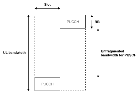
Bandwidth edges are used so that a large unfragmented portion of the spectrum remains to allocate to the PUSCH. If this spectrum was fragmented by multiple PUCCHs it would not be possible to allocate a number of contiguous RBs to a UE, hence the single carrier nature of SC-FDMA would be lost.
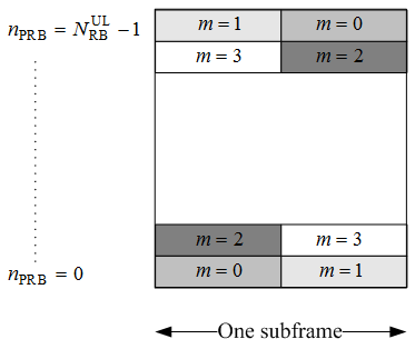
There is a single index, m, derived from the PUCCH resource index and other parameters that specifies the location of the PUCCH in time/frequency. When m is 0, the PUCCH occupies the lowest RB in the first slot and the highest RB in the second slot of a subframe. When m is 1, the opposite corners are used—the highest RB in the first slot and the lowest RB in the second slot. As m increases further, the allocated resource blocks move in towards the band center as shown in the following figure.
The resource for PUCCH formats 2, 2a, and 2b is indicated by a single scalar value called resource index. From this value, the cyclic shift can be determined. Time and frequency allocated resources are not derived from this value. However, higher layers are in full control of when and where control information is transmitted.
References
[1] 3GPP TS 36.212. “Evolved Universal Terrestrial Radio Access (E-UTRA); Multiplexing and channel coding.” 3rd Generation Partnership Project; Technical Specification Group Radio Access Network. URL: https://www.3gpp.org.
See Also
ltePUCCH2 | ltePUCCH2Indices | ltePUCCH2DRS | ltePUCCH2DRSIndices | lteULResourceGrid