Multi-Injection Diesel Calibration Workflow
Multi-Injection Diesel Problem Definition
Systematically develop a set of optimal steady-state multi-injection diesel engine calibration tables using Model-Based Calibration Toolbox™.
The engine to be calibrated is a 3.1L multi-injection combustion ignition engine with common rail, variable-geometry turbocharger (VGT), and cooled exhaust gas recirculation (EGR).
The aim of the calibration is to minimize brake-specific fuel consumption (BSFC) at specific speed/load operating points across the engine’s operating range, and meet these constraints:
Limit total NOx emissions.
Limit maximum turbocharger speed.
Limit calibration table gradients for smoothness.
The analysis must produce optimal calibration tables in speed and torque for:
Best main start of injection timing
Best total injected fuel mass per cylinder per cycle
Best pilot injection timing relative to main timing
Best pilot injection fuel mass fraction of total injection mass
Best exhaust gas recirculation (EGR) position
Best variable geometry turbocharger (VGT) vane position
Best fuel rail pressure relative to nominal pressure vs. engine speed
These sections explain the objectives of selecting best values for these calibration tables and the effects of these control variables on the engine:
Select the Turbocharger Position to Control Air-Charge and EGR
Select the EGR Valve Position to Control Air-Charge and Emissions
Select Main Injection Timing for Efficiency
You select the injection timing of the main fuel injection to maximize engine efficiency. You aim to make peak cylinder pressure occur slightly after piston top center. You inject fuel just before top-center compression, as shown.
Then you can achieve peak combustion pressure just after top-center expansion.
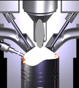
You also need to adjust injection timing according to speed and other conditions.
You need to advance (move earlier before piston top center) the start of injection timing with increasing speed and dilution (exhaust gas recirculation or EGR).
You need to retard the start of injection timing with increased fresh air intake (load).
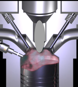
Select Pilot Injection Timing to Control Noise
You select the timing of the pilot fuel injection to start combustion early before the larger main fuel injection. The pilot fuel injection occurs well before top-center compression and before the main injection.
You can use pilot fuel injection to control combustion noise, because it affects the variability in cylinder pressure.
In this example, pilot fuel injection timing is defined as a crank-angle delta offset before the main injection, and is therefore a relative quantity.
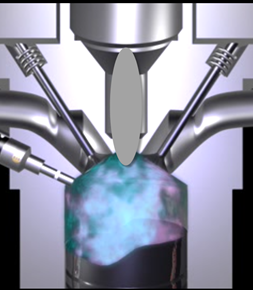
Select Main Fuel Mass for Efficiency and Emissions
The air-fuel ratio (AFR) affects engine efficiency and emissions. A rich AFR causes high engine-out particulates and low engine-out NOx. You control AFR by changing the main fuel mass for optimal balance between power and emissions.
The AFR of the combustion mixture is determined by the main fuel injection mass for a given amount of fresh air. The amount of air results mainly from EGR valve position, VGT position, intake throttle position, and speed.
Select Fuel Pressure for Efficiency and Emissions
You can use fuel pressure to control fuel droplet size. Reduced fuel droplet size in the combustion chamber reduces particulates, releases more energy from the fuel, and achieves more stable combustion. High fuel pressure decreases fuel droplet size to improve efficiency and emissions.
At low loads, you can use lower fuel pressure to decrease fuel pump power losses without much effect on emissions and power efficiency.
In this example, fuel pressure is controlled relative to an engine-speed-dependent base level via a fuel pressure delta, and is therefore a relative quantity.
Select the Turbocharger Position to Control Air-Charge and EGR
You can use the variable-geometry turbocharger (VGT) position to balance fresh air and exhaust gas recirculation for optimal NOx control at a given power level.
You can change VGT vane position to increase cylinder fresh air due to the turbocharger speed increase. With the vanes closed, the turbocharger moves faster (high VGT speed) and sends a higher load (or boost) of air into the engine. Closing the vanes also increases exhaust gas recirculation (EGR) due to increased backpressure from the closed vanes.
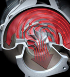
With the vanes open, VGT speed is low and passes through low load (or boost) to the engine.
Select the EGR Valve Position to Control Air-Charge and Emissions
You can use the EGR valve position to control the flow of burned exhaust gases back to the intake manifold.
Reburning exhaust gases decreases in-cylinder temperature, resulting in a significant decrease in NOx emissions.
If you select too much EGR for a given amount of injected fuel, then the air-fuel ratio will be rich, causing increased soot emissions. Therefore, you must balance these competing objectives.
In engines, timing is everything. Using the EGR valve and all the other control variables, controlling the engine's air flow is the key to optimizing fuel economy, reducing emissions, and increasing power density.
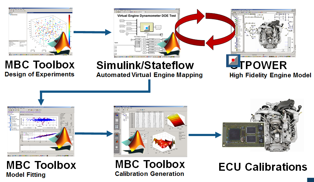
Engine Calibration Workflow
The following graphic illustrates the workflow for the model-based calibration process. The workflow can use a combination of tools: Model-Based Calibration Toolbox, Simulink®, Stateflow®, third-party high-fidelity simulation tools, and Hardware-in-the-Loop testing for fine tuning calibrations on ECUs.
Air-System Survey Testing
The first step to solve this calibration problem is to determine the boundaries of the feasible air-system settings. To do this, you create an experimental design and collect data to determine air-system setting boundaries that allow positive brake torque production in a feasible AFR range.
These simplifications were used to conduct the initial study:
Pilot injection is inactive.
Main timing is fixed.
Nominal fuel pressure vs RPM.
Main fuel mass is moved to match the AFR target.
Fit a boundary model to these design points.
Multi-Injection Testing
After the air-system survey, you have established the boundaries of positive brake torque air-system settings. Now, you can create an experimental design and collect data to gather fuel injection effects within those boundaries. You can then use this data to create response models for all the responses you need to create an optimal calibration for this engine.
Data Collection and Physical Modeling
The toolbox provides the data for you to explore this calibration example.
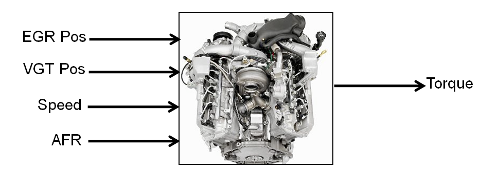
MathWorks® collected the data using simulation tools. Control and simulation models were constructed using Simulink and Stateflow. Constrained experimental designs were constructed using Model-Based Calibration Toolbox. The points specified in the design were measured using the GT-Power engine simulation tool from Gamma Technologies (see https://www.gtisoft.com).
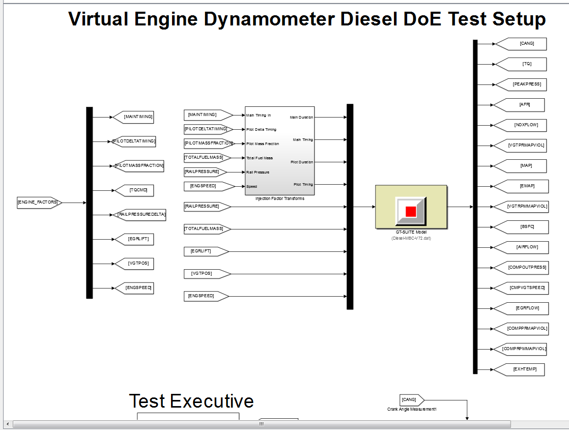
To collect the data, Simulink and Stateflow controlled the torque output of the GT-Power engine model to the desired Design of Experiments points using total fuel mass. This graphic shows the virtual dynamometer test model.
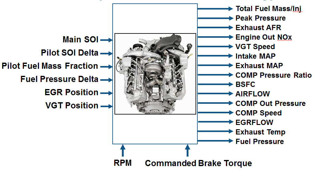
Statistical Modeling
After designing the experiments and collecting the data, you can fit statistical models to the data. You can use the toolbox to generate accurate, fast-running models from the measured engine data.
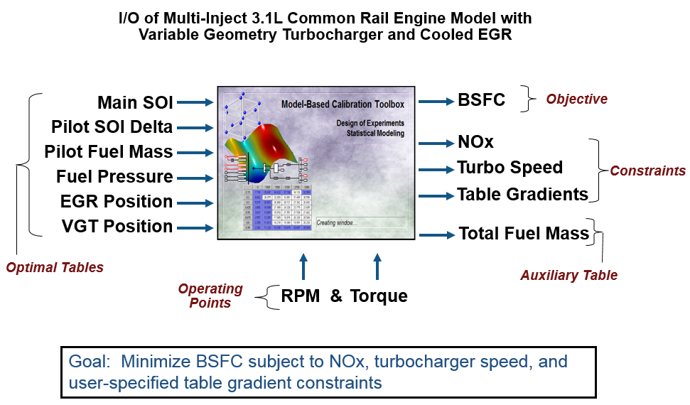
The following graphic shows the models to define in the toolbox to solve this calibration problem. The graphic shows how the model inputs and output relate to the optimal tables, optimization operating points, objectives and constraints you need to perform the optimization and create the calibration.
Optimization Using Statistical Models
After creating statistical models to fit the data, you can use them in optimizations. You can use the accurate statistical engine model to replace the high-fidelity simulation and run much faster, enabling optimizations to generate calibrations.
Run an optimization to choose whether to use Pilot Injection at each operating point.
Optimize fuel consumption over the drive cycle, while meeting these constraints:
Constrain total NOx
Constrain turbocharger speed
Constrain smoothness of tables
Fill lookup tables for all control inputs.
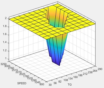
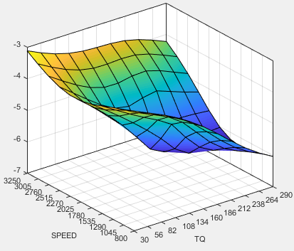
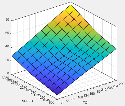
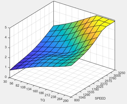
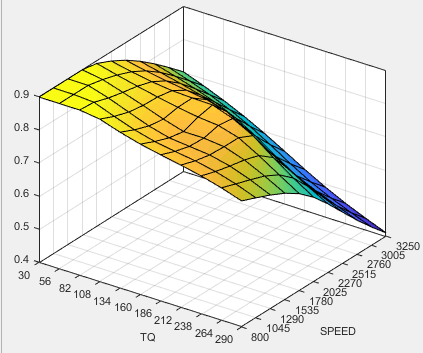
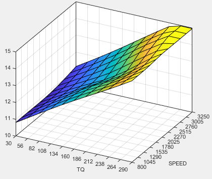
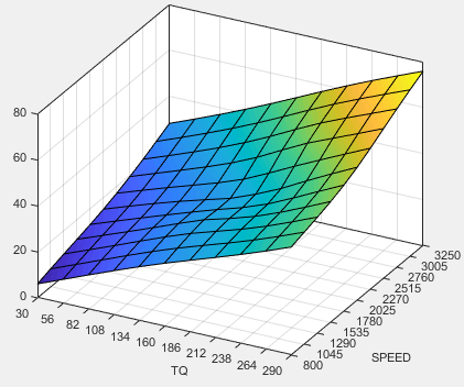
The following plots show a preview of the calibration results.
.
Pilot Mode Table
You need to fill calibration tables for each control variable described in Multi-Injection Diesel Problem Definition, in both pilot modes, active and inactive.
Following are all the pilot active tables.
Main Start of Injection (SOI) Timing Table
Total Injected Fuel Mass Table
Fuel Pressure Delta Table
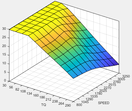
Exhaust Gas Recirculation (EGR) Valve Position Table
Variable-Geometry Turbo (VGT) Position Table
Pilot Injection Timing (Pilot SOI Delta) Table
Pilot Fuel Mass Fraction Table
Case Study Example Files
The following sections guide you through opening example files to view each stage of the model-based calibration process. You can examine:
Designs, constraints, boundary model, and collected data, in topic Design of Experiments for Multi-Injection Diesel Engine Calibration.
Finished statistical models, in topic Fit Empirical Models to Multi-Injection Diesel Engine Calibration Data.
Optimization setup and results, and filled calibration tables, in topic Optimize Multi-Injection Diesel Engine Calibration Using Statistical Models.
Use these example files to understand how to set up systematic calibrations for similar problems. For next steps, see Design of Experiments for Multi-Injection Diesel Engine Calibration.
Tip
Learn how MathWorks Consulting helps customers develop engine calibrations that optimally balance engine performance, fuel economy, and emissions requirements: see Optimal Engine Calibration.