How to Use Single Shunt FOC Library Blocks
This example shows how to use the Simulink blocks for single shunt FOC available with Motor Control Blockset™.
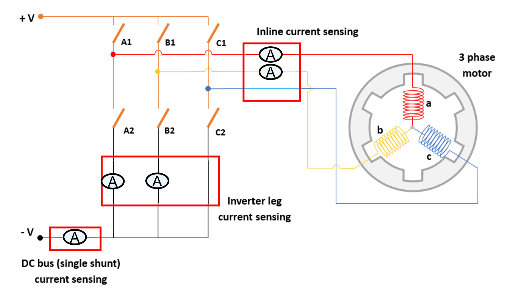
This example explains how to use the single shunt library blocks to reconstruct phase currents for Field-Oriented Control (FOC) using DC current measurements (single shunt), as shown in the below figure.
Running the Initialization section in this example configures the necessary workspace variables for model simulation. The subsequent sections detail the process of reconstructing phase currents:
DC Current Sampling: Accurate reconstruction of phase currents depends on sampling the DC current at precise intervals.
Current Mapping: The
Phase Current Extractor for Single Shunt FOCblock maps properly sampled DC currents to phase currents.PWM Pulse Shifting: The
PWM Phase Shift for Single Shunt FOCblock applies PWM shifting techniques to resolve sector crossing issues encountered during current mapping.
Initialization
Set up the Workspace for model simulation.
%% PWM and Simulation Timing Parameters % PWM switching frequency [Hz] PWM_frequency =20000; % PWM period [s] T_pwm = 1 / PWM_frequency; % Control sample time [s] (set equal to PWM period) Ts = T_pwm; % Simscape simulation step size [s] (100x faster than PWM period) Ts_motor_simscape = T_pwm / 100; %% PMSM Parameters % Select and load PMSM parameters % (Uncomment the appropriate line for your motor) pmsm = mcb.getPMSMParameters('BLY172S'); % Default: Anaheim Automation BLY172S % pmsm = mcb.getPMSMParameters('Teknic2310P'); % Alternative: Teknic 2310P %% Inverter Parameters % Load inverter parameters inverter = mcb.getInverterParameters('DRV8312-C2-KIT'); %% Base Speed Calculation % Calculate base speed of the motor at the specified DC bus voltage [rpm] pmsm.N_base = mcb.getMotorBaseSpeed(pmsm, inverter); %% Open-Loop Speed and Voltage Limits % Open-loop speed in per-unit [pu] Open_Loop_Speed =
0.2; % Maximum Vd for open-loop operation [pu] MAX_OL_VD_LIMIT =
0.6; % Minimum Vd for open-loop operation [pu] MIN_OL_VD_LIMIT =
0.15; % Note: If the motor fails to start due to high inertia, increase MIN_OL_VD_LIMIT %% PWM Compensation Parameters % Rise time of amplifier including power switches (MOSFET/IGBT) turn-on time [s] Trise = 100e-9; % Settling time of amplifier [s] Tsettle = 100e-9; % ADC Sample and Hold time [s] Tsh = 170e-9; % Dead-time between top and bottom switch [s] Tdeadtime = 150e-9; % Gate driver propagation delay [s] Tprop = 38e-9; % Total phase shift due to delays [s] Tdelay = Trise + Tsettle + Tsh + Tdeadtime + Tprop; % PWM compensation parameters structure PWMComp_params.thresold = Tdelay; % Threshold for activating PWM phase shift [s] PWMComp_params.shift = Tdelay; % Magnitude of phase shift applied to the PWM pulse [s]
Open the model.
open_system('SingleShuntWithRisingEdge');DC Current Sampling
To accurately reconstruct phase currents from the measured DC current in a three-phase inverter, it is critical to sample the DC current at precise time instants. For a clearer understanding, we can analyze the DC current waveform along with the phase PWM signals.
Run this section to simulate open-loop motor operation and visualize the inverter's DC current signal.
observeInverterCurrent(T_pwm);
The model SingleShuntWithRisingEdge is configured to simulate flush-to-zero (FTZ) behavior, but is using normal mode simulation. To observe FTZ behavior, simulate the model using an accelerated mode.
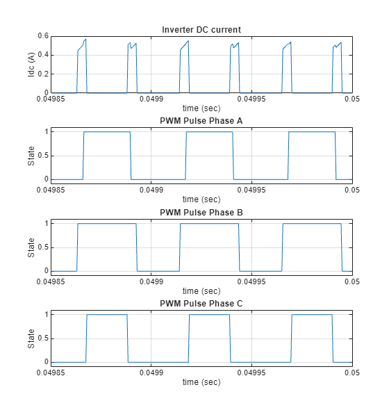
The diagram above demonstrates that when all upper-leg switches of the inverter are either simultaneously ON or OFF, the inverter DC current value is zero. Therefore, for accurate phase current reconstruction, current sampling must be performed exclusively during intervals when at least one upper-leg switch is ON and at least one is OFF, ensuring a valid current path through the inverter.
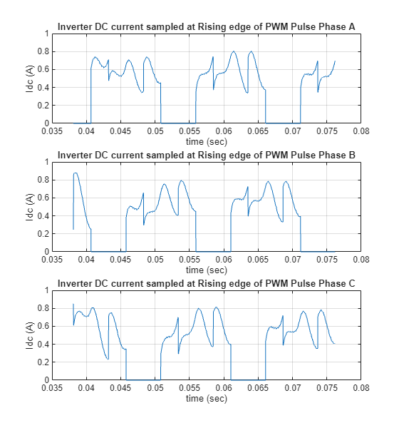
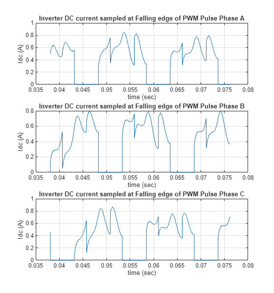
In this scenario, there are two viable options for sampling the inverter DC current: either near the rising edges of all three phase PWM pulses or near their respective falling edges. Sampling at these instances ensures that the switching states provide valid phase current information for accurate reconstruction.
observeInverterCurrentSampled(pmsm,Open_Loop_Speed,'RisingEdge');The model SingleShuntWithRisingEdge is configured to simulate flush-to-zero (FTZ) behavior, but is using normal mode simulation. To observe FTZ behavior, simulate the model using an accelerated mode.
observeInverterCurrentSampled(pmsm,Open_Loop_Speed,'FallingEdge');### Searching for referenced models in model 'SingleShuntWithFallingEdge'. ### Total of 1 models to build. ### Generating code for Physical Networks associated with solver block 'SingleShuntWithFallingEdge/Inverter and Motor/Solver Configuration' ... done. ### Building the rapid accelerator target for model: SingleShuntWithFallingEdge ### Successfully built the rapid accelerator target for model: SingleShuntWithFallingEdge
Current Mapping
Once the inverter DC current has been sampled at the appropriate instants, as described in the previous section, utilize the Phase Current Extractor for Single Shunt FOC library block to accurately map the measured DC current to the corresponding phase currents.
% Run this section to open the model, examine the integration of the Phase
% Current Extractor for Single Shunt FOC library block, and analyze the
% resulting outputs.
observePhaseCurrents(pmsm,Open_Loop_Speed,'RisingEdge','NoShift');
The model SingleShuntWithRisingEdge is configured to simulate flush-to-zero (FTZ) behavior, but is using normal mode simulation. To observe FTZ behavior, simulate the model using an accelerated mode.
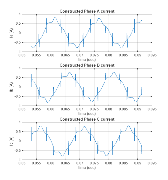
observePhaseCurrents(pmsm,Open_Loop_Speed,'FallingEdge','NoShift');
### Searching for referenced models in model 'SingleShuntWithFallingEdge'.
### Total of 1 models to build.
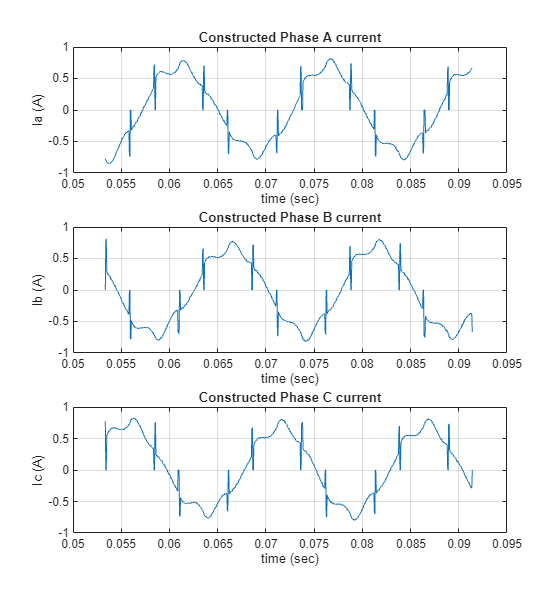
The diagram above illustrates that current mapping is unsuccessful at specific instances where any two PWM pulses have identical widths. This results in ambiguous phase current reconstruction. Addressing this issue is necessary and will be discussed in the next section.
PWM Pulse Shifting
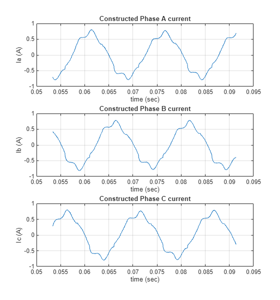
When the widths of two PWM pulses are nearly identical, a phase shift can be applied to one of the pulses to create an adequate sampling window for the inverter DC current. This approach ensures reliable current measurement and accurate phase current reconstruction.
Run this section to open the model, examine the integration of the PWM Phase Shift for Single Shunt FOC library block, and analyze the resulting outputs.
% PWM compensation parameters
PWMComp_params.thresold = Tdelay;% [sec] Threshold for PWM phase shift activation
PWMComp_params.shift    = Tdelay;% [sec] Amount of shift applied to the corresponding PWM pulse

% NOTE: When the phase shift logic causes a PWM pulse to overlap with the subsequent
% cycle's PWM pulse, the PWM Phase Shift output flag in the Single Shunt FOC library block
% is asserted (set high).

observePhaseCurrents(pmsm,Open_Loop_Speed,'RisingEdge','WithShift');
The model SingleShuntWithRisingEdge is configured to simulate flush-to-zero (FTZ) behavior, but is using normal mode simulation. To observe FTZ behavior, simulate the model using an accelerated mode.
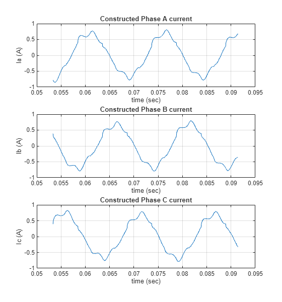
observePhaseCurrents(pmsm,Open_Loop_Speed,'FallingEdge','WithShift');
### Searching for referenced models in model 'SingleShuntWithFallingEdge'.
### Total of 1 models to build.
Hardware Requirements
These are the essential hardware requirements for the implementation of single-shunt Field-Oriented Control (FOC):
The hardware must support configurability of ADC sampling events to be precisely synchronized with either the rising or falling edge of the PWM signals.
The hardware must provide configurable PWM generation capabilities, enabling dynamic adjustment of phase shifts as required during operation.
For details, see Hardware Configuration for Single Shunt FOC.