Lane Keeping Assist with Lane Detection
This example shows how to simulate and generate code for an automotive lane keeping assist (LKA) controller.
In this example, you:
Review a control algorithm that combines data processing from lane detections and a lane keeping controller from the Model Predictive Control Toolbox™.
Test the control system in a closed-loop Simulink® model using synthetic data generated by the Automated Driving Toolbox™.
Configure the code generation settings for software-in-the-loop simulation and automatically generate code for the control algorithm.
Introduction
A lane keeping assist (LKA) system is a control system that aids a driver in maintaining safe travel within a marked lane of a highway. The LKA system detects when the vehicle deviates from a lane and automatically adjusts the steering to restore proper travel inside the lane without additional input from the driver. In this example, the LKA system switches between the driver steering command and lane keeping controller. This approach is sufficient to introduce a modeling architecture for an LKA system, however a real system would also provide haptic feedback to the steering wheel and enable the driver to override the LKA system by applying sufficient counter-torque.
For the LKA to work correctly, the ego vehicle must determine the lane boundaries and how the lane in front of it curves. Idealized LKA designs rely mostly on the previewed curvature, the lateral deviation, and relative yaw angle between the centerline of the lane and the ego vehicle. An example of such a system is given in Lane Keeping Assist System Using Model Predictive Control. Moving from advanced drive-assistance system (ADAS) designs to more autonomous systems, the LKA must be robust to missing, incomplete, or inaccurate measurement readings from real-world lane detectors.
This example demonstrates a robust approach to the controller design when the data from lane detections may not be accurate. To do so, it uses data from a synthetic lane detector that simulates the impairments introduced by a wide-angle monocular vision camera. The controller makes decisions when the data from the sensor is invalid or outside a range. This provides a safety guard when the sensor measurement is false due to conditions in the environment, such as a sharp curve on the road.
Get a list of systems that are open now so any systems opened during this example can be closed at the end.
startingOpenSystems = find_system('MatchFilter', @Simulink.match.allVariants);
Open Test Bench Model
To open the Simulink test bench model, use the following command.
open_system('LKATestBenchExample')
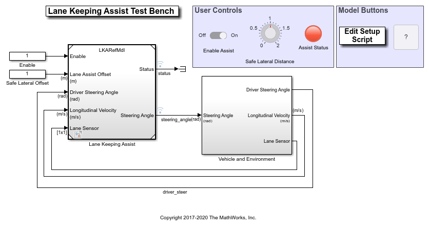
The model contains two main subsystems:
Lane Keeping Assist, which controls the front steering angle of the vehicle
Vehicle and Environment subsystem, which models the motion of the ego vehicle and models the environment
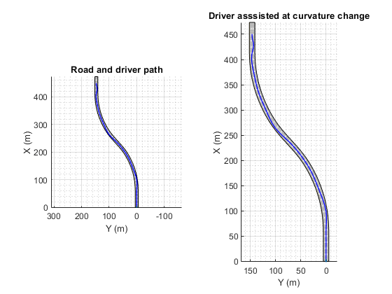
Opening this model also runs the helperLKASetUp script, which initializes data used by the model. The script loads certain constants needed by the Simulink model, such as the vehicle model parameters, controller design parameters, road scenario, and driver path. You can plot the road and the path that the driver model will follow.
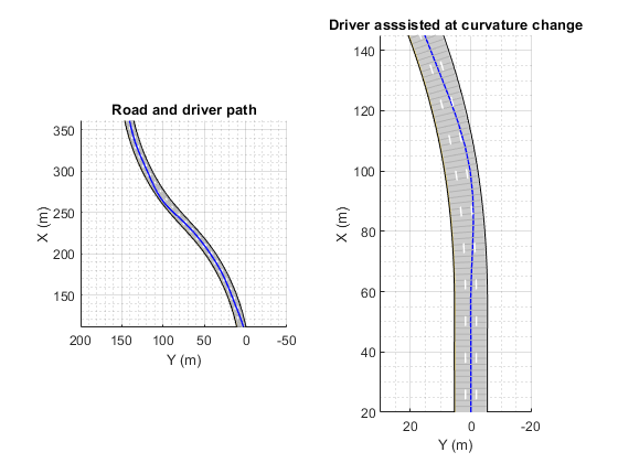
plotLKAInputs(scenario,driverPath)
Simulate Assisting a Distracted Driver
You can explore the behavior of the algorithm by enabling lane-keeping assistance and setting the safe lateral distance. In the Simulink model, in the User Controls section, switch the toggle to On, and set the Safe Lateral Distance to 1 meter. Alternatively, enable the lane-keeping assist and set the safe lateral distance.
set_param('LKATestBenchExample/Enable','Value','1')
set_param('LKATestBenchExample/Safe Lateral Offset','Value','1')
To plot the results of the simulation, use the Bird's-Eye Scope (Automated Driving Toolbox). The Bird's-Eye Scope is a model-level visualization tool that you can open from the Simulink toolstrip. On the Simulation tab, under Review Results, click Bird's-Eye Scope. After opening the scope, click Find Signals to set up the signals. Then run the simulation for 15 seconds, and explore the contents of the Bird's-Eye Scope.
sim('LKATestBenchExample','StopTime','15') % Simulate 15 seconds
   Assuming no disturbance added to measured output #1.
-->Assuming output disturbance added to measured output #2 is integrated white noise.
-->"Model.Noise" is empty. Assuming white noise on each measured output.

ans =

  Simulink.SimulationOutput:
                logsout: [1x1 Simulink.SimulationData.Dataset]
                   tout: [4682x1 double]

     SimulationMetadata: [1x1 Simulink.SimulationMetadata]
           ErrorMessage: [0x0 char]

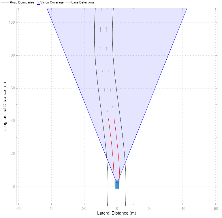
The Bird's-Eye Scope shows a symbolic representation of the road from the perspective of the ego vehicle. In this example, the Bird's-Eye Scope renders the coverage area of the synthetic vision detector as a shaded area. The ideal lane markings are additionally shown, as well as the synthetically detected left and right lane boundaries (shown here in red).
To run the full simulation and explore the results, use the following commands.
sim('LKATestBenchExample')                  % Simulate to end of scenario
plotLKAResults(scenario,logsout,driverPath)
   Assuming no disturbance added to measured output #1.
-->Assuming output disturbance added to measured output #2 is integrated white noise.
-->"Model.Noise" is empty. Assuming white noise on each measured output.


The blue curve for the driver path shows that the distracted driver may drive the ego vehicle to another lane when the road curvature changes. The red curve for the driver with Lane Keeping Assist shows that the ego vehicle remains in its lane when the road curvature changes.
To plot the controller performance, use the following command.
plotLKAPerformance(logsout)
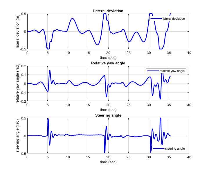
Top plot shows the lateral deviation relative to ego vehicle. The lateral deviation with LKA is within [-0.5,0.5] m.
Middle plot shows the relative yaw angle. The relative yaw angle with LKA is within [-0.15,0.15] rad.
Bottom plot shows the steering angle of the ego vehicle. The steering angle with LKA is within [-0.5,0.5] rad.
To view the controller status, use the following command.
plotLKAStatus(logsout)

Top plot shows the left and right lane offset. Around 5.5 s, 19 s, 31 s, and 33 s, the lateral offset is within the distance set by the lane keeping assist. When this happens, the lane departure is detected.
Middle plot shows the LKA status and the detection of lane departure. The departure detected status is consistent with the top plot. The LKA is turned on when the lane departure is detected, but the control is returned to the driver later when the driver can steer the ego vehicle correctly.
Bottom plot shows the steering angle from driver and LKA. When the difference between the steering angle from driver and LKA is small, the LKA releases control to driver (for example, between 9 s to 17 s).
Simulate Lane Following
You can modify the value of Safe Lateral Offset for LKA to ignore the driver input, putting the controller into a pure lane following mode. By increasing this threshold, the lateral offset is always within the distance set by the lane keeping assist. Thus, the status for lane departure is on and the lane keeping assist takes control all the time.
set_param('LKATestBenchExample/Safe Lateral Offset','Value','2')
sim('LKATestBenchExample')                                     % Simulate to end of scenario
   Assuming no disturbance added to measured output #1.
-->Assuming output disturbance added to measured output #2 is integrated white noise.
-->"Model.Noise" is empty. Assuming white noise on each measured output.

You can explore the results of the simulation using the following commands.
plotLKAResults(scenario,logsout)

The red curve shows that the Lane Keeping Assist on its own can keep the ego vehicle travelling along the centerline of its lane.
Use the following command to depict the controller performance.
plotLKAPerformance(logsout)

Top plot shows the lateral deviation relative to ego vehicle. The lateral deviation with LKA is within [-0.1,0.1] m.
Middle plot shows the relative yaw angle. The relative yaw angle with LKA is within [-0.02,0.02] rad.
Bottom plot shows the steering angle of the ego vehicle. The steering angle with LKA is within [-0.04,0.04] rad.
To view the controller status, use the following command.
plotLKAStatus(logsout)

Top plot shows the left and right lane offset. Since the lateral offset is never within the distance set by the lane keeping assist, the lane departure is not detected.
Middle plot shows that the LKA status is always one, that is, the Lane Keeping Assist takes control all the time.
Bottom plot shows the steering angle from driver and LKA. The steering angle from driver negotiating with the curved road is too aggressive. The small steering angle from LKA is sufficient for the curved road in this example.
Explore Lane Keeping Assist Algorithm
The Lane Keeping Assist model contains four main parts: 1) Estimate Lane Center 2) Lane Keeping Controller 3) Detect Lane Departure, and 4) Apply Assist.
open_system('LKATestBenchExample/Lane Keeping Assist')

The Detect Lane Departure subsystem outputs a signal that is true when the vehicle is too close to a detected lane. You detect a departure when the offset between the vehicle and lane boundary from the Lane Sensor is less than the Lane Assist Offset input.
The Estimate Lane Center subsystem outputs the data from lane sensors to the lane keeping controller. The detector in this example is configured to report the left and right lane boundaries of the current lane in the current field-of-view of the camera. Each boundary is modeled as a length of a curve whose curvature varies linearly with distance (clothoid curve). To feed this data to a controller, offset both of the detected curves toward the center of the lane by the width of the car and a small margin (1.8 m total). Weight each of the resulting centered curves by the strength of the detection and pass the averaged result to the controller. Also, The Estimate Lane Center subsystem provides finite values for inputs to the Lane Keeping Controller subsystem. The previewed curvature provides the centerline of lane curvature ahead of the ego vehicle. In this example, the ego vehicle can look ahead for three seconds, which is the product of the prediction horizon and sample time. This look-ahead time enables the controller to use previewed information for calculating steering angle for the ego vehicle, which improves the MPC controller performance.
The goal for the Lane Keeping Controller block is to keep the vehicle in its lane and follow the curved road by controlling the front steering angle  . This goal is achieved by driving the lateral deviation
  and the relative yaw angle
  to be small (see the following figure).

The LKA controller calculates a steering angle for the ego vehicle based on the following inputs:
Previewed curvature (derived from Lane Detections)
Ego vehicle longitudinal velocity
Lateral deviation (derived from Lane Detections)
Relative yaw angle (derived from Lane Detections)
Considering physical limitations of the ego vehicle, the steering angle is constrained to be within [-0.5,0.5] rad. You can change the prediction horizon or move the Controller Behavior slider to adjust the performance of the controller.
The Apply Assist subsystem decides if the lane keeping controller or the driver takes control of the ego vehicle. The subsystem switches between the driver commanded steering and the assisted steering from the Lane Keeping Controller. The switch to assisted steering is initiated when a lane departure is detected. Control is returned to the driver when the driver begins steering within the lane again.
Explore Vehicle and Environment
The Vehicle and Environment subsystem enables closed loop simulation of the lane keeping assist controller.
open_system('LKATestBenchExample/Vehicle and Environment')
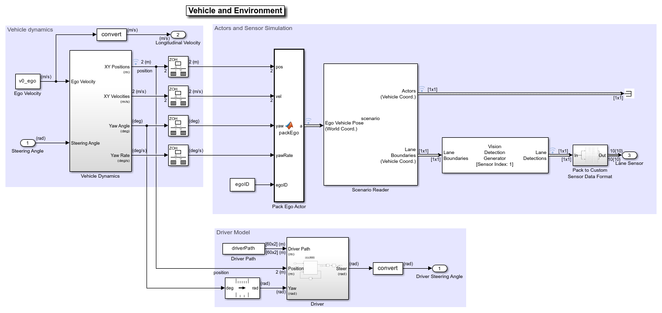
The Vehicle Dynamics subsystem models the vehicle dynamics with Vehicle Body 3DOF Single Track block from Vehicle Dynamics Blockset™.
The Scenario Reader (Automated Driving Toolbox) block generates the ideal left and right lane boundaries based on the position of the vehicle with respect to the scenario read from scenario file LKATestBenchScenario.mat.
The Vision Detection Generator block takes the ideal lane boundaries from the Scenario Reader block. The detection generator models the field of view of a monocular camera and determines the heading angle, curvature, curvature derivative, and valid length of each road boundary, accounting for any other obstacles.
The Driver subsystem generates the driver steering angle based on the driver path which was created in helperLKASetUp.
Generate Code for the Control Algorithm
The LKARefMdl model is configured to support generating C code using Embedded Coder® software. To check if you have access to Embedded Coder, run:
hasEmbeddedCoderLicense = license('checkout','RTW_Embedded_Coder')
You can generate a C function for the model and explore the code generation report by running:
if hasEmbeddedCoderLicense
    slbuild('LKARefMdl')
end
You can verify that the compiled C code behaves as expected using software-in-the-loop (SIL) simulation. To simulate the LKARefMdl referenced model in SIL mode, use:
if hasEmbeddedCoderLicense
    set_param('LKATestBenchExample/Lane Keeping Assist',...
        'SimulationMode','Software-in-the-loop (SIL)')
end
When you run the LKATestBenchExample model, code is generated, compiled, and executed for the LKARefMdl model. This allows you to test the behavior of the compiled code through simulation.
Conclusions
This example shows how to implement an integrated lane keeping assist (LKA) controller on a curved road with lane detection. It also shows how to test the controller in Simulink using synthetic data generated by the Automated Driving Toolbox, componentize it, and automatically generate code for it.
% Close any systems opened during execution of this example.
endingOpenSystems = find_system('MatchFilter', @Simulink.match.allVariants);
bdclose(setdiff(endingOpenSystems,startingOpenSystems))
See Also
Blocks
Related Examples
More About
You can also select a web site from the following list:
Americas
- América Latina (Español)
- Canada (English)
- United States (English)
Europe
- Belgium (English)
- Denmark (English)
- Deutschland (Deutsch)
- España (Español)
- Finland (English)
- France (Français)
- Ireland (English)
- Italia (Italiano)
- Luxembourg (English)
- Netherlands (English)
- Norway (English)
- Österreich (Deutsch)
- Portugal (English)
- Sweden (English)
- Switzerland
- United Kingdom (English)