plcimportladder
Import ladder diagram into a Simulink subsystem
Syntax
Description
[generates a Simulink representation of the ladder diagram in the L5X file with properties specified using one or more mdlname,mdllib,genbusscript] = plcimportladder(filename,Name,Value)Name,Value pair arguments.
Examples
Simulate, test, and validate your .L5X ladder diagram files by importing your ladder diagram files into Simulink®. Use the plcimportladder function to import your ladder diagram files into Simulink. Simulink PLC Coder™ supports only import of ladder diagram files created by using Rockwell Automation® RSLogix 5000® and Studio 5000 ® integrated development environments (IDEs).
Ladder Diagram Description
The ladder diagram in the simple_timer.L5X file controls a motor by using an input switch Switch_A and a timer Motor_timer. This ladder diagram was created using the Studio 5000 IDE.
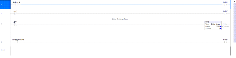
Light1, Light2, and Motor are the outputs of this ladder diagram.
Import Ladder Diagram
Before using the plcimportladder function to import your ladder diagram files into Simulink:
Verify that your .
L5Xladder diagram file has no errors by compiling the file in the Rockwell Automation IDE.Verify that the
.L5Xladder diagram file uses blocks that are supported by Simulink PLC Coder. For a list of supported blocks at the MATLAB® command line, enter:
plcladderlib
If your ladder diagram contains custom instructions that are not supported use the
Custom Instructionblock to create your instructions in Simulink. For more information, see Custom Instruction. To create a custom instruction, see Create Custom Instruction in PLC Ladder Diagram Models.
To import the simple_timer.L5X ladder diagram file into Simulink, use the plcimportladder function.
plcimportladder('simple_timer.L5X');The ladder diagram is imported into Simulink and a simple_timer.slx file is created. The current folder also contains a simple_timer_value.mat file that loads the initial values for Motor_timer into the model data store memory. The data store memory also contains state information of elements of the ladder diagram. This state information is updated by the model during simulation.
During the ladder diagram import, Simulink PLC Coder:
Imports rung comments. For example, rung two of
simple_timer.L5Xhas the commentMotor On Delay Timer. This comment also appears in the Simulink model as well.Imports Add On Instruction (AOI) with mixed-order arguments, while preserving the order of the arguments. This order argument is preserved during ladder diagram code generation as well.
Imported Ladder Diagram Structure
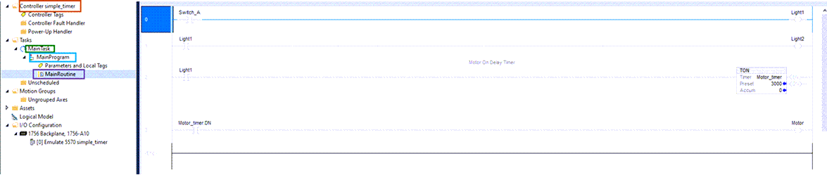
The simple_timer.L5X ladder diagram file is located in Controller simple_timer > MainTask > MainProgram > MainRoutine.
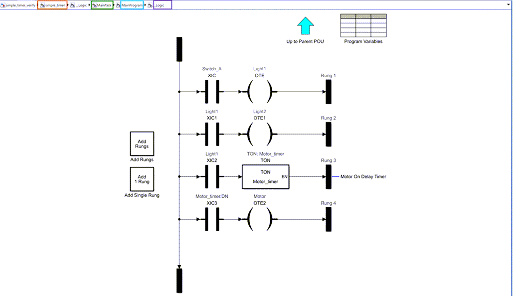
The simple_timer.slx ladder diagram is located in simple_timer > MainTask > MainProgram > _Logic. This structure is similar to the structure in the Rockwell Automation IDE.
Verify Imported Ladder Diagram
To verify the imported ladder diagram:
Open the
simple_timer.slxmodel. Open thesimple_timerblock, double-click Controller Tags and setSwitch_Ato Input Symbol andMotorto Output Symbol. Click OK.Add a Signal Editor block. Open the Signal Editor block interface and set the File Name to
verify_ladder.mat. Click OK.Add a Cast to Boolean block between the Signal Editor block and
Switch_A.Add a Scope block and connect the
Switch_AandMotorsignals to this block.

Open the
Scopeblock and click theRunbutton.
This image shows the Scope block output for the model simulation. The Motor output turns on three seconds after Switch_A is turned on and turns off as soon as Switch_A is turned off.

Input Arguments
Name-Value Arguments
Output Arguments
Version History
Introduced in R2018a
See Also
plcgeneraterunnertb | plcgeneratecode | plcladderlib | plcladderoption | plcloadtypes | plccleartypes