Main Content

microstripLineCustom

Create coupled form of single or differential microstrip transmission line

Since R2022b

Description

Use the microstripLineCustom object to create a coupled form of single or differential microstrip transmission line. A microstrip line is a transmission line that is a basic building block for most RF planar microwave devices. You can use this transmission line to connect two PCB components or to create components such as filters, couplers, and feeding elements of several types of antennas.

Three part image from right to left: Default image of a custom microstrip line. Current distribution on the custom microstrip line. S-parameters plot of the custom microstrip line.

A few applications of microstrip transmission lines are:

  • Creating matching feed and coupling networks

  • Transmitting power from one component to another

  • Feeding planar antennas and coupling structures

  • Creating varying inductances or capacitances using open- or short ended- transmission lines

Creation

Description

microstrip = microstripLineCustom creates a coupled form of single or differential microstrip transmission line. The default properties are for a design frequency of 2.5 GHz.

example

microstrip = microstripLineCustom(Name=Value) sets properties using one or more name value pair arguments. For example, microstrip = microstripLineCustom(TraceSpacing=0.0300) creates a custom differential microstrip transmission line with a trace spacing of 0.0300 meters. Properties not specified retain their default values.

Properties

expand all

Types of traces, specified as 'Single' or 'Differential'.

Example: microstrip = microstripLineCustom(TraceType='Differential')

Data Types: string | char

Length of the trace in meters, specified as a positive scalar.

Example: microstrip = microstripLineCustom(TraceLength=0.0371)

Data Types: double

Width of the trace in meters, specified as a positive scalar.

Example: microstrip = microstripLineCustom(TraceWidth=0.0041)

Data Types: double

Spacing between the two traces of a differential pair in meters, specified as a positive scalar. Set the TraceType property to 'Differential' to enable this property.

Example: microstrip = microstripLineCustom(TraceSpacing=0.0041)

Data Types: double

Position to offset reference trace along the X-axis, specified as a positive scalar.

Example: microstrip = microstripLineCustom(TraceOffsetX=0.5)

Data Types: double

Height from the custom microstrip line to the ground plane in meters, specified as a positive scalar.

In the case of a multilayer substrate, you can use the height property to create a microstrip line at the interface of the two dielectrics.

Example: microstrip = microstripLineCustom(Height=0.0026)

Data Types: double

Length of the ground plane in meters, specified as a positive scalar.

Example: microstrip = microstripLineCustom(GroundPlaneLength=0.0500)

Data Types: double

Gap between the left coupled traces in meters, specified as a scalar or vector. Set this property to 0, if there are no left coupled traces.

Example: microstrip = microstripLineCustom(LeftCoupledTraceGap=0)

Data Types: double

Gap between the right coupled traces in meters, specified as a scalar or vector. Set this property to 0, if there are no right coupled traces.

Example: microstrip = microstripLineCustom(RightCoupledTraceGap=0)

Data Types: double

Type of dielectric material used as a substrate, specified as a dielectric object. The dielectric material in a microstriplineCustom with default properties is Teflon. The thickness of the default dielectric material Teflon is 0.0016 m or the same as the height property.

Example: d = dielectric('FR4'); microstrip = microstripLineCustom(Substrate=d)

Type of metal used in conducting layers, specified as a metal object. The type of metal in a microstriplineCustom object with default properties is PEC.

Example: m = metal('PEC'); microstrip = microstripLineCustom(Conductor=m)

Flag to add a metal shielding to the PCB component, specified as a logical 0 or logical 1. The default value is logical 0.

Example: IsShielded = true or 1 add a metal shield.

Note

To enable FEM solver required for the metal shield property, download the Integro-Differential Modeling Framework for MATLAB. To download this add-on:

  1. In the Home tab Environment section, click on Add-Ons. This opens the add-on explorer. You need an active internet connection to download the add-on.

  2. Search for Integro-Differential Modeling Framework for MATLAB and click Install.

  3. To verify if the download is successful, run

    matlab.addons.installedAddons
    in your MATLAB® session command line.

  4. On Windows, to run the IDMF add-on, you must install the Windows Subsystem for Linux (WSL). To install WSL, see Install Linux on Windows with WSL.

    The Windows Defender Firewall can block the PostgreSQL server when using the IDMF add-on. To resolve this issue, you can allow the server to communicate on desired networks if the firewall prompts. Alternatively, you can manually add the executable file of the PostgreSQL server located in <matlabroot>\sys\postgresql\win64\PostgreSQL\bin\postgres.exe. For more information regarding firewalls, see Allowing apps through Windows Defender Firewall .

Data Types: logical

This property is read-only.

Metal shield for the PCB component, specified as a shape.Box object. The length and width of the box must be equal to the length and width of the ground plane. The center of the box is at [0 0 Shielding.Height]. You can modify the property after creating the object.

Dependencies

To enable the Shielding property, set the IsShielded property to true or 1.

Type of RF connector assembled at the feed locations of the PCB component, specified as a RFConnector object.

Example: Create connector from RFConnector object like this: coaxial = RFConnector adds a coaxial connector.

Dependencies

To enable the Connector property, set the IsShielded property to true or 1.

Object Functions

chargeCalculate and plot charge distribution
currentCalculate and plot current distribution
designDesign microstrip transmission line around specified frequency
feedCurrentCalculate current at feed port
getZ0Calculate characteristic impedance of transmission line
layoutPlot all metal layers and board shape
meshChange and view mesh properties of metal or dielectric in PCB component
shapesExtract all metal layer shapes of PCB component
showDisplay PCB component structure or PCB shape
sparametersCalculate S-parameters for RF PCB objects
RFConnectorCreate RF connector

Examples

collapse all

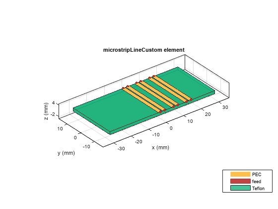
Create a coupled form of differential microstrip line with two pairs of right coupled lines.

microstrip = microstripLineCustom(TraceType='Differential',TraceWidth=...
    0.002,TraceSpacing=0.0005,RightCoupledTraceGap=[0.003,0.003],...
    LeftCoupledTraceGap=0);

View the custom transmission line.

show(microstrip)

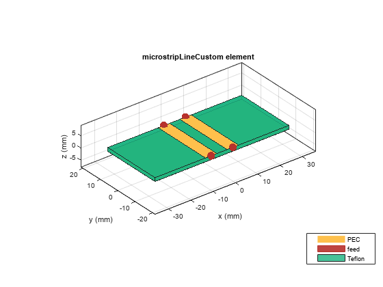
Create a differential microstrip transmission line with no left or right traces

microstrip = microstripLineCustom(TraceType='Differential',TraceSpacing=...
    0.0046,LeftCoupledTraceGap=0,RightCoupledTraceGap=0);

View the transmission line.

show(microstrip)

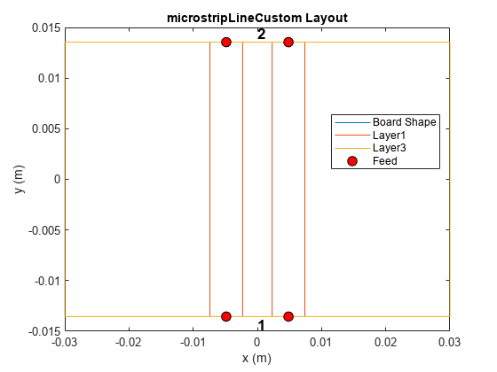
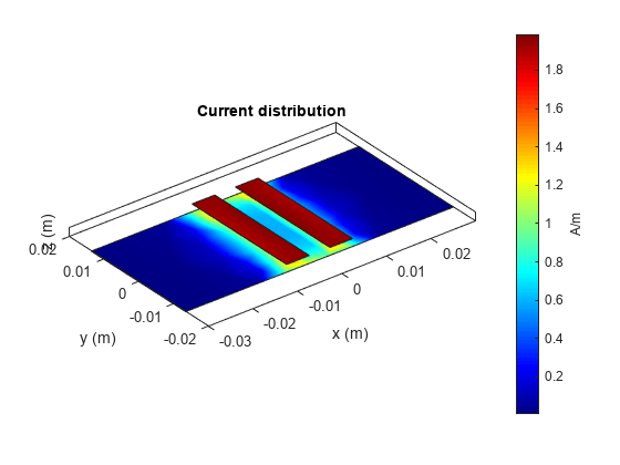
Set the voltage on the transmission line ports. View the layout.

v = voltagePort(4);
v.FeedVoltage = [1 0 1 0];
v.FeedPhase = [0 0 180 0];
figure;
layout(microstrip)

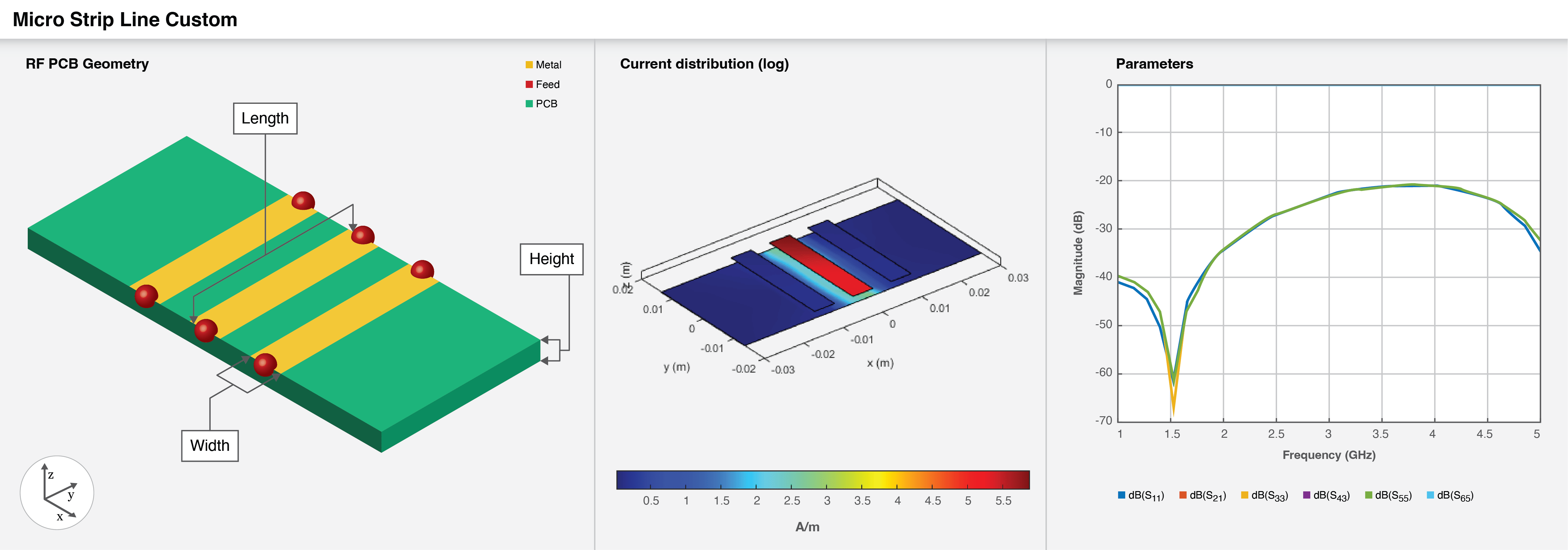
Analyze the current at 2.5 GHz.

figure;
current(microstrip,2.5e9,Excitation=v)

References

[1] Pozar, David M. Microwave Engineering. 4th ed. Hoboken, NJ: Wiley, 2012.

Version History

Introduced in R2022b

expand all