Generate Standalone ROS Node from Simulink
This example shows you how to generate and build a standalone ROS node from a Simulink® model.
Introduction
In this example, you configure a model to generate C++ code for a standalone ROS node. You then build and run the ROS node on an Ubuntu® Linux® system.
Prerequisites
This example requires Simulink Coder™.
A Ubuntu Linux system with ROS and an SSH server installed is necessary for building and running the generated C++ code. You can use your own Ubuntu ROS system, or you can use the Linux virtual machine used for Robotics System Toolbox™ examples (see Get Started with Gazebo and Simulated TurtleBot for instructions).
Review the Feedback Control of a ROS-Enabled Robot example.
Configure a Model for Code Generation
Configure a model to generate C++ code for a standalone ROS node. The model is the proportional controller introduced in the Feedback Control of a ROS-Enabled Robot example.
Open
RobotController.slx. Click the link or runRobotControllerin the Command Window.In the Prepare section under ROS tab, click Hardware Settings to open the Hardware Implementation pane of the Configuration Parameters dialog. The Hardware board settings section contains settings specific to the generated ROS package, such as information to be included in the
package.xmlfile. Change Maintainer name toROS Example User.The model uses variable-sized arrays. If you have Embedded Coder™ installed, you must enable code-generation for variable-sized signals. Check variable-size signals under Code Generation > Interface > Software environment. If the variable-size signals option is not visible, check the option, Use Embedded Coder Features in Hardware Implementation > Advanced parameters
.In the Solver pane of the Configuration Parameters dialog, ensure that Solver Type is set to Fixed-step, and set Fixed-step size to
0.05. In generated code, the Fixed-step size defines the actual time step, in seconds, that is used for the model update loop (see Execution of Code Generated from a Model (Simulink Coder)). It can be made smaller (e.g., 0.001 or 0.0001) but for current purposes 0.05 is sufficient.
Configure the Connection to the ROS Device
A ROS device is any Linux system that has ROS installed and is capable of building and running a ROS node. If you have Simulink Coder, you can generate code for a standalone ROS node. If your system is connected to a ROS device, Simulink can also transfer the generated code to the ROS device, build an executable, and run the resulting ROS node (this is referred to as "deploying" the ROS node).
In this task, you decide if you want to generate code for the ROS node or if you want to build and run it on a ROS device. If you are connected to a ROS device, you can configure Simulink to use it as a deployment target for your ROS node.
Under the Modeling tab, click Model Settings.
In the Hardware Implementation pane of Configuration Parameters dialog, select an Build action under Hardware board settings > Target hardware resources > Groups > Build Options. The selected build action affects the behavior of Simulink when building the model. None (the default setting) only generates the code for the ROS node, without building it on an external ROS device. Build and load generates the code, transfers it to an external device and builds a ROS node executable. If you select Build and run, the resulting node executable is started automatically at the end of the build.
Set the Build action to Build and run.
Configure the connection to your external ROS device. Under the ROS tab, from the Deploy to drop-down, click Manage Remote Device. This opens the Connect to a ROS device dialog. In this dialog, you can enter all the information that Simulink needs to deploy the ROS node. This includes the IP address or host name of your ROS device, your login credentials, and the Catkin workspace. Change Catkin workspace to
~/catkin_ws_test.
ROS Folder is the location of the ROS installation on the ROS device. If you do not specify this folder, the settings test (see next step) tries to determine the correct folder for you.

If the ROS device is turned on and accessible from your computer, you can verify the connection settings by clicking Test. The test verifies every device setting and display warnings and errors in the Simulink Diagnostic Viewer if problems are found. If possible, the test also suggests how the problems can be fixed. Click Test now.
Most likely, the Catkin workspace
~/catkin_ws_testdoes not exist on the target device. The test detects this problem and suggests to create the folder and initialize the workspace. Click Fix to apply this action automatically. After a few seconds, you should see a green notice that the folder has been created successfully. In the following figure you can see an example of creating the folder successfully. To verify that the Catkin workspace is now available, click Test in the connection settings dialog again. The warning has disappeared and the Catkin workspace is ready to build your ROS node.

Change the device connection settings and test them until no other warnings or errors are shown. If an automatic fix to your settings is possible, Simulink suggests it by displaying the Fix button. Once you have a good set of settings, click OK in the connection settings dialog to save the settings.
The connection settings are not specific to a single model, but apply to all ROS models in Simulink.
Generate the C++ ROS Node
Generate code for a standalone ROS node, and automatically transfer, build, and run it on the ROS device. Exercise the generated ROS node using a ROS master running on the ROS device.
1. In MATLAB®, change the current folder to a temporary location where you have write permission.
2. The code generation process first prepares the model for simulation to ensure that all blocks are properly initialized. This preparation requires a valid connection to a ROS master.
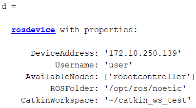
In MATLAB, you can use the rosdevice object to start a ROS master on the ROS device. If you provide no arguments, rosdevice uses the device connection settings you entered in the Simulink dialog to connect to the ROS device.
d = rosdevice
runCore(d);

3. Use rosinit to connect MATLAB to the ROS master running on the ROS device:
rosinit(d.DeviceAddress)
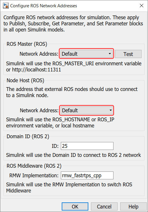
4. Tell Simulink to use the same ROS connection settings as MATLAB. Under the Simulation tab, in Prepare section, select ROS Network. Set the ROS Master (ROS 1) and Node Host network addresses to Default.

You only have to execute steps 2 - 4 once per MATLAB session, not every time you generate a ROS node.
5. Under ROS tab, from the Deploy Type section, select the deployment type as Standard Node.
6. Under the ROS tab, click Deploy > Build & Run. If you get any errors about bus type mismatch, close the model, clear all variables from the base MATLAB workspace, and re-open the model.
Click on the View Diagnostics link at the bottom of the model toolbar to see the output of the build process.
7. Once the code generation completes, the ROS node is transferred to the Catkin workspace on your ROS device. The node builds there and starts to run automatically in a synchronous fashion based on the sample time of the model.
The generated node connects to the ROS master running on the ROS device.
8. Use rosnode to list all running nodes is the ROS network. "robotcontroller" should be in the displayed list of nodes.
rosnode list
You can use rostopic to verify that the deployed node publishes data on the ROS topic to control the robot motion:
rostopic info /mobile_base/commands/velocity
Run and Verify the ROS Node
Run the newly-built ROS node and verify its behavior using a MATLAB-based robot simulator.
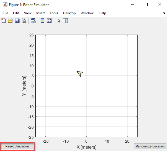
1. In MATLAB, type ExampleHelperSimulinkRobotROS to start the Robot Simulator. The simulator automatically connects to the ROS master running on the ROS device. If you want to connect to a Gazebo-based robot simulation, see Connect to ROS-enabled Robot from Simulink.
sim = ExampleHelperSimulinkRobotROS

2. Verify that the simulated robot moves toward the goal (the Desired Position constant specified in the model). The robot stops once it reaches the goal [-10, 10].
3. Click Reset Simulation to reset the robot's position to [0, 0]. The robot starts to move immediately towards the goal position.
4. In MATLAB, you can manage ROS nodes generated by Simulink with the rosdevice object. Once a Simulink model is deployed, you can use rosdevice to run and stop the node at any point, without having to rebuild it in Simulink.
The AvailableNodes property shows the deployed robotcontroller node. You can verify that the node is running by calling the isNodeRunning function.
d = rosdevice

isNodeRunning(d, 'robotcontroller')
5. Stop the ROS node from running.
stopNode(d, 'robotcontroller')
isNodeRunning(d, 'robotcontroller')
6. Click the Reset Simulation button in the simulation window. The robot stays at location [0,0] and does not move.
Now restart the node.
runNode(d, 'robotcontroller')
The robot should start moving towards the goal position again.
7. Once you are done verifying, you can clean up the system state as follows.
Stop the node running on the target device
stopNode(d, 'robotcontroller')
On the host computer, close the Robot Simulator figure window and type
rosshutdownat the MATLAB command line.
rosshutdown
Advanced Topics and Troubleshooting
Specify code generation and build options: You can choose different code generation and build behaviors by specifying one of these Deployment options from the toolstrip under ROS tab.
Generate code — Generates the ROS package source code on localhost or remote device.
Build Model — Generates the ROS package source code and builds the standalone executable on localhost or remote device.
Build & Run — Generates the ROS package source code, builds the standalone executable and starts running it on localhost or remote device.
Specify ROS network settings in Simulink: By default, Simulink uses the ROS connection settings from rosinit in MATLAB. To override these settings, specify ROS connection settings in Simulink. Under the Simulation tab, in Prepare section, select ROS Network and set the ROS Master and Node Host network addresses:

Specify external ROS packages as dependencies: To specify external ROS packages as dependencies to the generated ROS node, specify appropriate toolchain options. In the Configuration parameters, under Code Generation > Toolchain Settings, specify the Build configuration as Specify from the drop-down. Then, you can specify the Required Packages, Include Directories, Link Libraries, Library Paths and Defines based on the external ROS packages that you wish to integrate with the generated ROS node.
Specify custom source and include files: You can specify custom source and include files in the configuration parameters, under Simulation Target > Custom Code. In the Code Information section, specify Include headers, Include directories and Source files. In the configuration parameters, under Code Generation > Custom Code, select Use the same custom code settings as Simulation Target.
Generated C++ code archive: No matter what Build action you select (None, Build and load, Build and run), Simulink always generates two files in your current folder: an archive containing the C++ source code (RobotController.tgz in our example) and a shell script for extracting and building the C++ code manually (build_ros_model.sh). If your MATLAB computer is not connected to the ROS device, you can transfer the files manually and build them there. Ensure that build_ros_model.sh is set up as an executable on your ROS device by entering the following command:
chmod +x build_ros_model.sh

Processor-specific generated code: If you use blocks from other products (such as Computer Vision System Toolbox™), the generated code may include processor-specific optimizations that lead to compilation problems when building the ROS node on Linux. In these cases, you need to let Simulink know the platform on which the generated code is compiled. You can do this through the Hardware Implementation pane of the Model Configuration Parameters dialog.
Running ROS Master in MATLAB: In the example above, you connected to a ROS master running on the ROS device. Alternatively, you can create a ROS master in MATLAB. Use rosinit at the MATLAB command line:
rosinit('NodeHost', <IP address of your computer>)
For example, if the IP address of your host computer is 172.18.250.92, use the following command:
rosinit('NodeHost', '172.18.250.92')
The NodeHost setting is important to ensure that the generated ROS node is able to communicate to the master on MATLAB. Note: The generated ROS node will use the NodeHost IP address to communicate to the global ROS node in MATLAB, so ensure that the specified IP address is accessible from the ROS device (for example, using ping). See the Connect to a ROS Network example for more details on the significance of the NodeHost setting.
Tasking mode: Simulink can generate code for either multi-tasking or single-tasking modes (see Time-Based Scheduling and Code Generation (Simulink Coder)). By default, generated ROS code uses single-tasking mode (a single thread for all the rates) without real-time scheduling. This allows the generated ROS code to execute without sudo privileges, but can lead to less predictable performance.
If you require more predictable performance, you can configure the model to use multi-tasking. In the Solver pane of the Configuration Parameters dialog enable Treat each discrete rate as a separate task to enable multi-tasking. In generated code, this creates a separate thread for each rate in the model and uses prioritized scheduling for the threads.
To run the ROS node, you need to have administrative privileges on the ROS device. Simulink automatically detects if your privileges are insufficient when the model is deployed to the target device.