Enable a Gate for a Time Interval
Behavior of Entity Gate Block in Enabled Mode
The Entity Gate block uses a control signal at the input port at the top of the block to determine when the gate is open or closed:
When an entity with a positive payload arrives at the enable port at the top of the block, the gate is open and an entity can arrive as long as it would be able to advance immediately to the next block.
When an entity with zero or negative payload arrives at the enable port at the top of the block, the gate is closed and no entity can arrive.
Because that incoming signal can remain positive for a time interval of arbitrary length, an enabled gate can remain open for a time interval of arbitrary length. The length can be zero or a positive number.
Depending on your application, the gating logic can arise from time-driven dynamics, state-driven dynamics, a SimEvents® block's statistical output signal, or a computation involving various types of signals. To see the ready-to-use common design patters including the Entity gate block, see SimEvents Common Design Patterns.
Sense an Entity Passing from A to B and
                    Open a Gate
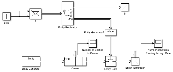
This example shows how to use the Sense an Entity Passing from A to B and
Open a Gate design pattern. In this example, the Step block generates a step signal
at time 4. This signal passes through the Send block A. The Entity Replicator block duplicates
the entity and passes it to B. It uses the original entity to trigger an event-based
entity to enable the Entity Gate block.
In a new model, drag the above blocks, relabel and connect them as shown in the example. For convenience, start with the
Sense an Entity
                            Passing from A to B and Open a Gate
design pattern.In the Step block, set the Step time parameter to
4.In the A (Message Send) block, select the Show enable port check box. Selecting this check box lets the Step block signal enable the A block to send a message to the Entity Replicator block.
In the Entity Generator block, in the Entity type tab:
Name the entity type
Entity.Add an attribute named
Capacitywith an initial value of0.
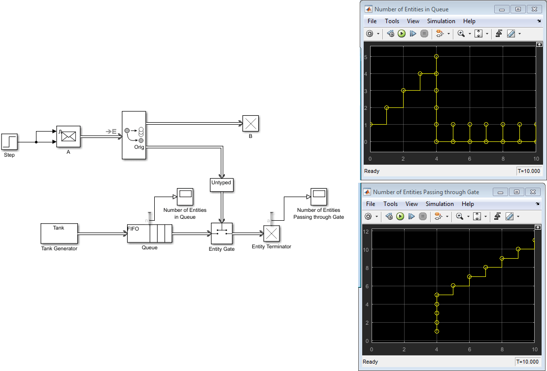
In the Entity Queue block, in the Statistics tab, select Number of entities in block, n.
Save and run the model. Observe the number of entities passing through the gate and the number of entities in the queue at time 4.
Control Joint Availability of Two Servers
Suppose that each entity undergoes two processes, one at a time, and that the first process does not start if the second process is still in progress for the previous entity. Assume for this example that it is preferable to model the two processes using two Single Server blocks in series rather than one Single Server block whose service time is the sum of the two individual processing times; for example, you might find a two-block solution more intuitive or you might want to access the two Single Server blocks' utilization output signals independently in another part of the model.
If you connect a queue, a server, and another server in series, then the first server can start serving a new entity while the second server is still serving the previous entity. This does not accomplish the stated goal. The model needs a gate to prevent the first server from accepting an entity too soon, that is, while the second server still holds the previous entity.
See Also
Entity Input Switch | Entity Output Switch | Entity Replicator | Entity Gate | Send