Main Content

PMSM (Six-Phase, Symmetrical)

R2026b

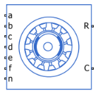
Symmetrical six-phase permanent magnet synchronous motor with sinusoidal flux distribution

Since R2026b

  • PMSM (Six-Phase, Symmetrical) block

Libraries:
Simscape / Electrical / Electromechanical / Permanent Magnet

Description

The PMSM (Six-Phase, Symmetrical) block models a permanent magnet synchronous motor (PMSM) with a six-phase star-wound, hexagon-wound, or hexagram-wound stator. Use this block to model these types of motor, if the motor has six stator windings:

  • Interior PMSM (IPMSM)

  • Surface PMSM (SPMSM)

  • Axial flux (pancake) motor

  • PMSM servomotor.

This figure shows the equivalent electrical circuit for the star-connected stator windings.

Equivalent electrical circuit for the PMSM with star-connected stator windings

To model the PMSM in a hexagon-wound or a hexagram-wound configuration, set the Winding type parameter to Hexagon-wound or Hexagram-wound, respectively.

These figures show the equivalent electrical circuits for the hexagon-wound and hexagram-wound stator windings.
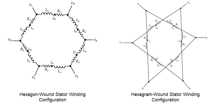
Equivalent electrical circuit for the PMSM with hexagon-wound and hexagram-wound stator windings

Permanent magnets generate a rotor magnetic field that creates a sinusoidal rate of change of flux based on the rotor angle. For the axes convention:

  • When you set the Rotor angle definition parameter to Angle between the a-phase magnetic axis and the d-axis, the a-phase and permanent magnet fluxes align when the rotor mechanical angle θr is zero.

  • When you set the Rotor angle definition parameter to Angle between the a-phase magnetic axis and the q-axis, the rotor mechanical angle is the angle between the a-phase magnetic axis and the rotor q-axis.

Equations

The voltages across the stator windings are

[vavbvcvdvevf]=[Rs000000Rs000000Rs000000Rs000000Rs000000Rs][iaibicidieif]+[dψadtdψbdtdψcdtdψddtdψedtdψfdt],

where:

  • va, vb, vc, vd, ve, and vf are the individual phase voltages across the stator windings.

  • Rs is the equivalent resistance of each stator winding.

  • ia, ib, ic, id, ie, and if are the currents flowing in the stator windings.

  • dψadt, dψbdt, dψcdt, dψddt, dψedt, and dψfdt are the rates of change for the magnetic flux in each stator winding.

The permanent magnet and the six windings contribute to the total flux linking each winding. The total flux is

[ψaψbψcψdψeψf]=[LaaLabLacLadLaeLafLbaLbbLbcLbdLbeLbfLcaLcbLccLcdLceLcfLdaLdbLdcLddLdeLdfLeaLebLecLedLeeLefLfaLfbLfcLfdLfeLff][iaibicidieif]+[ψamψbmψcmψdmψemψfm],

where:

  • ψa, ψb, ψc, ψd, ψe, and ψf are the total fluxes that link each stator winding.

  • Laa, Lbb, Lcc, Ldd, Lee, and Lff are the self-inductances of the stator windings. These self-inductances are functions of the rotor electrical angle, θe, and depend on the stator per-phase self-inductance, Ls, and the stator inductance fluctuation, Lm.

    • θe=Nθr+rotoroffset where θr is the rotor mechanical angle.

    • rotor offset is 0 if you define the rotor electrical angle with respect to the d-axis, or -pi/2 if you define the rotor electrical angle with respect to the q-axis.

    • Ls is the stator per-phase self-inductance. This value is the average self-inductance of each of the stator windings.

    • Lm is the stator inductance fluctuation. This value is the amount that the self-inductance and mutual inductance fluctuate with the changing of the rotor angle.

  • Lab, Lac, Lba, and so on, are the mutual inductances of the stator windings. These mutual inductances are functions of the rotor electrical angle, θe. They depend on the stator mutual inductance, Ms, and the stator per-phase self-inductance, Ls.

    • Ms is the stator mutual inductance. This value is the average mutual inductance between the stator windings.

  • ψam, ψbm, ψcm, ψdm, ψem, and ψfm are the permanent magnet fluxes linking the stator windings.

The permanent magnet flux linking winding a-a' is at maximum when θe = 0° and zero when θe = 90°. Therefore, the linked motor flux is equal to:

[ψamψbmψcmψdmψemψfm]=[ψmcosθeψmcos(θeπ3)ψmcos(θe2π3)ψmcos(θeπ)ψmcos(θe+2π3)ψmcos(θe+π3)],

where ψm is the permanent magnet flux linkage.

Simplified Electrical Equations

Applying a decoupled transformation to the block electrical equations produces an expression for torque that is independent of the rotor angle.

The decoupled transformation is equal to:

P(θe)=13[cosθecos(θeπ3)cos(θe2π3)cos(θeπ)cos(θe+2π3)cos(θe+π3)sinθesin(θeπ3)sin(θe2π3)sin(θeπ)sin(θe+2π3)sin(θe+π3)10.50.510.50.503232032320.50.50.50.50.50.50.50.50.50.50.50.5].

The transformation matrix, P, has this pseudo-orthogonal property:

P1(θe)=3PT(θe).

Using the P transformation on the stator winding voltages and currents transforms them into the dq0 and xy frames, which are independent of the rotor angle. These equations calculate the voltages and currents in the dq0and xy frames

[vdsvqsvxvyv01v02]=P(θe)[vavbvcvdvevf]

[idsiqsixiyi01i02]=P(θe)[iaibicidieif]

where:

  • vds, vqs, vx, vy, v01, and v02 are the d-axis, q-axis, x-axis, y-axis, and zero-sequence stator voltages.

  • ids, iqs, ix, iy, i01, and i02 are the d-axis, q-axis, x-axis, y-axis, and zero-sequence stator currents.

Applying this transformation to the electrical equations produces these equations:

vds=Rsids+LddidsdtNωiqsLqvqs=Rsiqs+LqdiqsdtNω(idsLd+ψm)vx=Rsix+L0dixdtvy=Rsiy+L0diydtv01=Rsi01+L0di01dtv02=Rsi02+L0di02dtT=3N[iqs(idsLd+ψm)idsiqsLq]

where:

  • Ld=Ls+Ms+3Lm is the stator d-axis inductance.

  • Lq=Ls+Ms3Lm is the stator q-axis inductance.

  • L0=Ls5Ms is the stator zero-sequence inductance.

  • ω is the rotor mechanical rotational speed.

  • N is the number of rotor permanent magnet pole pairs.

  • T is the torque.

Alternative Flux Linkage Parameterization

You can parameterize the motor by using the back electromotive force (EMF) or torque constants, which are more commonly given on motor datasheets, by using the Permanent magnet flux linkage parameter.

The back EMF constant is the peak voltage induced by the permanent magnet in the per-unit rotational speed of each of the phases. The relationship between the peak permanent magnet flux linkage and the back EMF is:

ke=Nψm.

The back EMF, eph, for one phase is:

eph=keω.

The torque constant is the peak torque induced by the per-unit current of each of the phases. It is numerically identical in value to the back EMF constant when both are expressed in SI units:

kt=Nψm.

When Ld = Lq and the currents in all six phases are balanced, the combined torque T is:

T=3ktiqs=3ktIpk,

where Ipk is the peak current in any of the six windings.

The block obtains the factor 3 from the steady-state sum of the torques from all phases. Therefore, the torque constant kt can also be:

kt=13(TIpk),

where T is the measured total torque when testing with a balanced three-phase current with a peak line current of Ipk. Using the RMS line voltage, the torque constant kt is:

kt=26(TIline,rms).

Model Thermal Effects

You can expose thermal ports to model the effects of losses that convert power to heat. To expose the thermal ports, set the Modeling option parameter to either:

  • No thermal port — The block contains expanded electrical conserving ports associated with the stator windings, but does not contain thermal ports.

  • Show thermal port — The block contains expanded electrical conserving ports associated with the stator windings and thermal conserving ports for each of the windings and for the rotor.

For more information about using thermal ports in actuator blocks, see Simulating Thermal Effects in Rotational and Translational Actuators.

Variables

To set the priority and initial target values for the block variables before simulation, use the Initial Targets section in the block dialog box or Property Inspector. For more information, see Set Priority and Initial Target for Block Variables.

Nominal values provide a way to specify the expected magnitude of a variable in a model. Using system scaling based on nominal values increases the simulation robustness. You can specify nominal values using different sources, including the Nominal Values section in the block dialog box or Property Inspector. For more information, see System Scaling by Nominal Values.

Ports

Conserving

expand all

Electrical conserving port associated with the stator winding a.

Electrical conserving port associated with the stator winding b.

Electrical conserving port associated with the stator winding c.

Electrical conserving port associated with the stator winding d.

Electrical conserving port associated with the stator winding e.

Electrical conserving port associated with the stator winding f.

Electrical conserving port associated with the neutral point of the windings configuration.

Dependencies

To enable this port, set Zero sequence to Include and Winding type to Star-wound.

Mechanical rotational conserving port associated with the motor rotor.

Mechanical rotational conserving port associated with the motor case.

Electrical conserving port associated with the end 1 of the stator winding a.

Dependencies

To enable this port, set Winding type to Open-end.

Electrical conserving port associated with the end 1 of the stator winding b.

Dependencies

To enable this port, set Winding type to Open-end.

Electrical conserving port associated with the end 1 of the stator winding c.

Dependencies

To enable this port, set Winding type to Open-end.

Electrical conserving port associated with the end 1 of the stator winding d.

Dependencies

To enable this port, set Winding type to Open-end.

Electrical conserving port associated with the end 1 of the stator winding e.

Dependencies

To enable this port, set Winding type to Open-end.

Electrical conserving port associated with the end 1 of the stator winding f.

Dependencies

To enable this port, set Winding type to Open-end.

Electrical conserving port associated with the end 2 of the stator winding a.

Dependencies

To enable this port, set Winding type to Open-end.

Electrical conserving port associated with the end 2 of the stator winding b.

Dependencies

To enable this port, set Winding type to Open-end.

Electrical conserving port associated with the end 2 of the stator winding c.

Dependencies

To enable this port, set Winding type to Open-end.

Electrical conserving port associated with the end 2 of the stator winding d.

Dependencies

To enable this port, set Winding type to Open-end.

Electrical conserving port associated with the end 2 of the stator winding e.

Dependencies

To enable this port, set Winding type to Open-end.

Electrical conserving port associated with the end 2 of the stator winding f.

Dependencies

To enable this port, set Winding type to Open-end.

Thermal conserving port associated with the stator winding a.

Dependencies

To enable this port, set Modeling option to Show thermal port.

Thermal conserving port associated with the stator winding b.

Dependencies

To enable this port, set Modeling option to Show thermal port.

Thermal conserving port associated with the stator winding c.

Dependencies

To enable this port, set Modeling option to Show thermal port.

Thermal conserving port associated with the stator winding d.

Dependencies

To enable this port, set Modeling option to Show thermal port.

Thermal conserving port associated with the stator winding e.

Dependencies

To enable this port, set Modeling option to Show thermal port.

Thermal conserving port associated with the stator winding f.

Dependencies

To enable this port, set Modeling option to Show thermal port.

Thermal conserving port associated with the rotor.

Dependencies

To enable this port, set Modeling option to Show thermal port.

Parameters

expand all

Whether to enable the thermal ports of the block and model the effects of losses that convert power to heat.

Main

Configuration for the stator windings:

  • Star-wound — The windings are star-wound.

  • Hexagon-wound — The windings are hexagon-wound. The a-phase is connected between ports a and b, the b-phase between ports b and c, the c-phase between ports c and d, the d-phase between ports d and e, the e-phase between ports e and f, and the f-phase between ports f and a.

  • Hexagram-wound — The windings are hexagram-wound. The a-phase is connected between ports b and f, the b-phase between ports a and c, the c-phase between ports b and d, the d-phase between ports c and e, the e-phase between ports d and f, and the f-phase between ports e and a.

  • Open-end — The windings are in an open-end configuration. The block exposes each end of the windings as electrical connections.

Number of permanent magnet pole pairs on the rotor.

Permanent magnet flux linkage, specified as Specify flux linkage, Specify torque constant, or Specify back EMF constant.

Peak permanent magnet flux linkage for any of the stator windings.

Dependencies

To enable this parameter, set Permanent magnet flux linkage parameterization to Specify flux linkage.

Torque constant for each of the stator windings.

Dependencies

To enable this parameter, set Permanent magnet flux linkage parameterization to Specify torque constant.

Back EMF constant for each of the stator windings.

Dependencies

To enable this parameter, set Permanent magnet flux linkage parameterization to Specify back EMF constant.

Specify how to parameterize the stator inductances of the motor:

  • Specify Ld, Lq, and L0 — Use the dq-axis synchronous inductances of the motor.

  • Specify Ls, Lm, and Ms — Use the phase inductances of the motor.

Direct-axis inductance, representing the stator inductance when the stator current vector is aligned with the rotor magnetic axis.

Dependencies

To enable this parameter, set Stator parameterization to Specify Ld, Lq, and L0.

Quadrature‑axis inductance, representing the inductance when the stator current is orthogonal to the rotor magnetic axis.

Dependencies

To enable this parameter, set Stator parameterization to Specify Ld, Lq, and L0.

Zero‑sequence inductance, representing the stator inductance associated with the zero‑sequence current components.

Dependencies

To enable this parameter, set Stator parameterization to Specify Ld, Lq, and L0.

Average self-inductance of each of the six stator windings.

Dependencies

To enable this parameter, set Stator parameterization to Specify Ls, Lm, and Ms.

Amount that the self-inductance and mutual inductance of the stator windings fluctuate with the rotor angle.

Dependencies

To enable this parameter, set Stator parameterization to Specify Ls, Lm, and Ms.

Average mutual inductance between each pair of adjacent stator windings.

Dependencies

To enable this parameter, set Stator parameterization to Specify Ls, Lm, and Ms.

Resistance of each of the stator windings.

Whether to include or exclude zero-sequence terms.

  • Include — Include zero-sequence terms. Select this option to prioritize model fidelity. Using this option results in an error for simulations that use the Partitioning solver. For more information, see Increase Simulation Speed Using the Partitioning Solver.

  • Exclude — Exclude zero-sequence terms. Select this option to prioritize simulation speed for desktop simulation or real-time deployment.

Dependencies

To enable this parameter, set Winding type to Star-wound.

Reference point for the rotor angle measurement. When you select the default value, Angle between the a-phase magnetic axis and the d-axis, the rotor and a-phase fluxes align when the rotor angle is zero.

When you select Angle between the a-phase magnetic axis and the q-axis, the a-phase current generates maximum torque when the rotor angle is zero.

Mechanical

Inertia of the rotor attached to the mechanical rotational port R.

Mechanical damping coefficient applied to the rotor rotational dynamics.

Thermal

Temperature at which the block rates the motor parameters.

Dependencies

To enable this parameter, set Modeling option to Show thermal port.

Coefficient α in the equation relating resistance to temperature for all six windings, as described in Thermal Model for Actuator Blocks. The default value, 3.93e-3 1/K, is for copper.

Dependencies

To enable this parameter, set Modeling option to Show thermal port.

Fractional rate at which the permanent magnet flux density changes with temperature. Use this parameter to linearly reduce the torque and the induced back EMF as temperature rises.

Dependencies

To enable this parameter, set Modeling option to Show thermal port.

Thermal mass value for each stator winding. The thermal mass is the energy required to raise the temperature by one degree.

Dependencies

To enable this parameter, set Modeling option to Show thermal port.

Thermal mass of the rotor. The thermal mass is the energy required to raise the temperature of the rotor by one degree.

Dependencies

To enable this parameter, set Modeling option to Show thermal port.

References

[1] Yepes, Alejandro G., et al. "Comparison of Stator Winding Connections in Multiphase Drives under Healthy Operation and with One Open Converter Leg". IET Electric Power Applications, vol. 14, no. 4, Apr. 2020, pp. 584–96. DOI.org (Crossref), https://doi.org/10.1049/iet-epa.2019.0467.

Extended Capabilities

expand all

C/C++ Code Generation
Generate C and C++ code using Simulink® Coder™.

Version History

Introduced in R2026b