Main Content

Simulink.BlockDiagram.getInitialState

Get initial state data from block diagram

Description

x0 = Simulink.BlockDiagram.getInitialState(mdlName) compiles the model specified by mdlName and returns the initial values for block states in the model, including states for blocks inside referenced models.

  • If the Format parameter value for the model is Dataset, then x0 is a Simulink.SimulationData.Dataset object that contains the initial state information for blocks in the model.

  • If the Format parameter for the model is anything other than Dataset, then x0 is a structure that contains the initial state information for blocks in the model.

You can use this initial state information to specify initial block state values for simulation or to provide an initial condition for linearization. You can use the state information as-is, or you can modify individual state values or remove state values from the structure if you want to specify state information for a subset of block states.

To simulate a model from an initial simulation state or operating point, consider using a Simulink.op.ModelOperatingPoint object instead. The ModelOperatingPoint object contains complete information about the model operating point, including block states, hidden block states, the state of the solver and execution engine, and output values for some blocks. For more information, see Specify Initial State for Simulation.

example

Examples

collapse all

Open the model vdp. The model uses two Integrator blocks.

mdl = "vdp";
open_system(mdl)

The model vdp.

The Format parameter for the model specifies whether the Simulink.BlockDiagram.getInitialState function returns a structure or a Simulink.SimulationData.Dataset object. Set the parameter value to Dataset.

  1. In the Simulink® Toolstrip, on the Modeling tab, click Model Settings.

  2. In the Configuration Parameters dialog box, select the Data Import/Export pane.

  3. From the Format list, select Dataset.

  4. In the Configuration Parameters dialog box, click OK.

Alternatively, use the set_param function to specify the value for the SaveFormat parameter.

set_param(mdl,"SaveFormat","Dataset")

Get the Dataset object of block states for the model using the Simulink.BlockDiagram.getInitialState function.

initStates = Simulink.BlockDiagram.getInitialState(mdl)
initStates = 
Simulink.SimulationData.Dataset 'xFinal' with 2 elements

                        Name  BlockPath 
                        ____  _________ 
    1  [1x1 State]      ''    vdp/x1   
    2  [1x1 State]      ''    vdp/x2   

  - Use braces { } to access, modify, or add elements using index.

Set the value of the state for the Integrator block named x2 to 2.

initStates{2}.Values.Data = 2;

Remove the element with the state information for the Integrator block named x1.

initStates = removeElement(initStates,1);

Specify the variable initStates, which includes an initial state value for the Integrator block named x2 as the initial state for the model.

  1. In the Simulink Toolstrip, on the Modeling tab, click Model Settings.

  2. In the Configuration Parameters dialog box, select the Data Import/Export pane.

  3. Select Initial state. Then, in the box, enter initStates.

  4. Click OK.

Alternatively, use the set_param function to configure the LoadInitialState and InitialState parameters.

set_param(mdl,"LoadInitialState","on","InitialState","initStates")

Simulate the model.

out = sim(mdl);

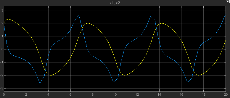
To view the output signals for both Integrator blocks, double-click the Scope block. For both Integrator blocks, the initial output value and initial state value are both 2.

The Scope block displays the output signals for the Integrator blocks named x1 and x2.

For the Integrator block named x2, the initial state value of 2 comes from the value of the Initial state parameter. For the Integrator block named x1, the initial state value of 2 is specified in the block parameters.

blk = strcat(mdl,"/x1");
get_param(blk,"InitialCondition")
ans = 
'2'

Open the model vdp. The model uses two Integrator blocks.

mdl = "vdp";
open_system(mdl)

The model vdp.

The Format parameter for the model specifies whether the Simulink.BlockDiagram.getInitialState function returns a structure or a Simulink.SimulationData.Dataset object. Set the parameter value to Structure.

  1. In the Simulink® Toolstrip, on the Modeling tab, click Model Settings.

  2. In the Configuration Parameters dialog box, select the Data Import/Export pane.

  3. From the Format list, select Structure.

  4. In the Configuration Parameters dialog box, click OK.

Alternatively, use the set_param function to specify the value for the SaveFormat parameter.

set_param(mdl,"SaveFormat","Structure")

Get the structure of block states for the model using the Simulink.BlockDiagram.getInitialState function. The structure contains information for two block states in the signals field, one for each Integrator block.

initStates = Simulink.BlockDiagram.getInitialState(mdl)
initStates = struct with fields:
       time: 0
    signals: [1x2 struct]

The signals structure for each state contains information about the state, including the initial value currently used in the model and the block path.

initStates.signals(2)
ans = struct with fields:
               values: 0
           dimensions: 1
                label: 'CSTATE'
            blockName: 'vdp/x2'
            stateName: ''
    inReferencedModel: 0
           sampleTime: [0 0]

The second block state corresponds to the Integrator block named x2. Set the values field to 2.

initStates.signals(2).values = 2;

Remove the structure in the signals field that includes information about the state for the Integrator block named x1.

initStates.signals(1) = [];

Specify the variable initStates, which includes an initial state value for the Integrator block named x2 as the initial state for the model.

  1. In the Simulink Toolstrip, on the Modeling tab, click Model Settings.

  2. In the Configuration Parameters dialog box, select the Data Import/Export pane.

  3. Select Initial state. Then, in the box, enter initStates.

  4. Click OK.

Alternatively, use the set_param function to configure the LoadInitialState and InitialState parameters.

set_param(mdl,"LoadInitialState","on","InitialState","initStates")

Simulate the model.

out = sim(mdl);

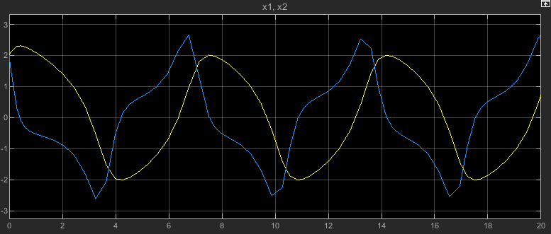
To view the output signals for both Integrator blocks, double-click the Scope block. The initial output value for the Integrator block is the initial state value. For both Integrator blocks, the initial output value and initial state value are both 2.

The Scope block displays the output signals for the Integrator blocks named x1 and x2.

For the Integrator block named x2, the initial state value of 2 comes from the value of the Initial state parameter. For the Integrator block named x1, the initial state value of 2 is specified in the block parameters.

blk = strcat(mdl,"/x1");
get_param(blk,"InitialCondition")
ans = 
'2'

Input Arguments

collapse all

Model name, specified as a string or a character vector.

Data Types: char | string

Output Arguments

collapse all

Initial values for block states, returned as a Simulink.SimulationData.Dataset object or as a structure.

When the Format parameter value for the model is Dataset, the initial state values are returned as a Dataset object.

Otherwise, the initial state values are returned as a structure that contains these fields:

  • time — Simulation time

  • signals1-by-n array of structures, where n is the number of block states in the model

Each structure in the signals field represents a block state and contains these fields:

  • values — State value

  • dimensions — Dimensions of state value

  • label — State label

    For continuous states, the state label is CSTATE. The name of the discrete state is shown for discrete states in S-Function blocks and for blocks that assign names to discrete states. For unnamed discrete states, the state label is DSTATE.

  • blockName — Full path to block associated with state

  • inReferencedModel — Logical indication of whether the state is associated with a block in a referenced model

    A value of 1 or true indicates that the state is associated with a block in a referenced model. A value of 0 or false indicates that the state is associated with a block in the top model.

  • sampleTime — Sample time information for the block associated with the state

    The value is a 1-by-2 array where the first element indicates the sample time and the second element indicates the sample time offset.

Version History

Introduced in R2006b