Migration to Service-Oriented Architecture Using Model-Based Design
This example shows the step-by-step migration of an electric vehicle software application from a monolithic model to a service-oriented architecture (SOA). SOA is a modern software architecture paradigm for building applications as a collection of modular units of software called services. This approach enables you to build complex and distributed applications in which you can update individual components, instead of building a large monolithic model. A typical SOA software stack consists of application software with services, platform services, and middleware. SOAs are becoming increasingly prevalent in the automotive industry with the shift towards using high-performance computing (HPC) systems, enabling more efficient and scalable vehicle software solutions.
When you migrate monolithic models to SOAs, you can:
Reuse and share services with many applications or components.
Upgrade services via over-the-air updates.
Relocate functions within the software architecture.
More easily test individual modules.
Migration to Service-Oriented Architecture Workflow Steps
To migrate a monolithic model to an SOA using Model-Based Design:
Generate baseline tests from the monolithic model using Simulink® Test™.
Refactor the software application into modular components based on the requirements of the system.
Develop a software architecture model and define service interfaces using System Composer™.
Specify component behavior using Simulink.
Perform regression testing on the migrated model.
Generate code using Embedded Coder®.
Click each box in the flow chart for more detail.
Service-Oriented Architecture Project
To load the project to your working folder, click the Copy Command button. The project contains folders that correspond to the example steps, with the files referenced throughout the example.
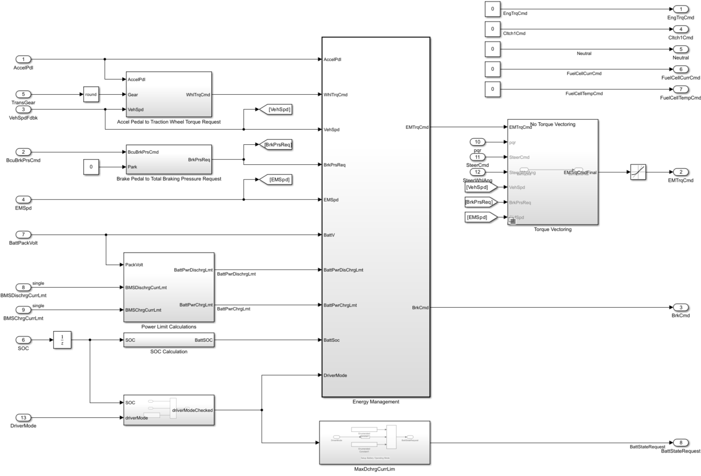
The electric vehicle control application in this example is responsible for managing motor torque arbitration and power. It determines the amount of motor torque and brake pressure to command. The control model implements these functions:
Torque request conversion — Converts the driver accelerator pedal signal to a torque request.
Brake pressure request conversion — Converts the driver brake pedal signal to a brake pressure request. The algorithm multiplies the brake pedal signal by a maximum brake pressure.
Regenerative braking — Recovers the maximum amount of kinetic energy from the vehicle.
Virtual battery management — Outputs the dynamic discharge and charge power limits as functions of battery state of charge (SOC).
Power management — Prevents the battery dynamic discharge and charge power limits from being exceeded.
This image shows the monolithic model from the EvPwrCntrllrEM.slx file.
See Also
Get Started with Virtual Vehicle Composer (Powertrain Blockset)