Print Models Programmatically
You can print Simulink® model diagrams and export them to image file formats programmatically.
Printing Commands
The MATLAB®
print command provides several printing options. For example, to print the
Compression subsystem in the sldemo_enginewc model
to your default printer, enter these commands in the MATLAB Command Window.
openExample('sldemo_enginewc');
print -sCompression
When you use the print command, you can print only one diagram. To
print multiple levels in a model hierarchy, use multiple print
commands, one for each diagram that you want to print.
Tip
Alternatively, consider printing interactively. In the Simulink Toolbar, on the Simulation tab, in the File section, click Print. Then, use the Print Model dialog box in the Simulink Editor to specify the diagrams to print. For details, see Select the Systems to Print.
You can use the set_param function with these parameters to
specify printing options for models.
Model Parameters for Printing
Parameter | Description | Values |
|---|---|---|
| Printing paper orientation. |
|
| Paper position mode.
|
|
| Printing paper type. |
|
| Printing paper size units. |
|
| Size of the margins associated with each tiled page. Each element in the vector represents a margin at the particular edge. | vector — |
Print Systems with Multiline Names or Names with Spaces
To print a system whose name appears on multiple lines, assign the name to a variable
and use that variable in the print command. This example shows how to
print the subsystem named Aircraft Dynamics Model.
openExample('simulink_aerospace/AircraftLongitudinalFlightControlExample')
open_system('slexAircraftExample/Aircraft Dynamics Model');
sys = sprintf('slexAircraftExample/Aircraft\nDynamics\nModel');
print (['-s' sys])
To print a system whose name includes one or more spaces, specify the name as a
character vector. For example, to print the Throttle & Manifold
subsystem, enter these commands.
openExample('sldemo_enginewc');
open_system('sldemo_enginewc/Throttle & Manifold');
print (['-sThrottle & Manifold'])
Set Paper Orientation and Type
To set just the paper orientation, use the orient function. Alternatively, set the paper orientation by using
set_param function with the PaperOrientation model
parameter.
To set the paper type, use the set_param function with the
PaperType model parameter. For example, to print to US letter-sized
paper, set the paper type to 'usletter'.
Print Diagrams over Multiple Pages
By default, each block diagram is scaled during the printing process so that the diagram fits on a single page. In the case of a large diagram, this automatic scaling can compromise the printed image.
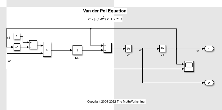
Tiled printing allows you to print even the largest block diagrams without sacrificing clarity and detail. Tiled printing allows you to distribute a block diagram over multiple pages. For example, you can use tiling to divide a model as shown in the figure, with each white box and each gray box representing a separate printed page.

Enable Tiled Printing
Use the
set_paramfunction to set thePaperPositionModeparameter totiled.Use the
printcommand with the-tileallargument.
For example, to enable tiled printing for the Compression subsystem
in the sldemo_enginewc model, use these commands.
openExample('sldemo_enginewc');
set_param('sldemo_enginewc/Compression', 'PaperPositionMode', ...
'tiled');
print('-ssldemo_enginewc/Compression', '-tileall')
Display Tiled Page Boundaries
To display the page boundaries programmatically, use the
set_param function with the model parameter
ShowPageBoundaries set to on.
openExample('sldemo_enginewc');
set_param('sldemo_enginewc', 'ShowPageBoundaries', 'on')
Set Tiled Page Margins
By decreasing the margin sizes, you can increase the printable area of the tiled
pages. To specify the margin sizes associated with tiled pages, use the
set_param function with the TiledPaperMargins
parameter. Each margin is 0.5 inches by default. The value of
TiledPaperMargins is a vector that specifies margins in this order:
[left top right bottom]. Each element specifies the size of the
margin at a particular edge of the page. The value of the PaperUnits
parameter determines the units of measurement for the margins.
Specify Range of Tiled Pages to Print
To specify a range of tiled page numbers programmatically, use the
print command with the -tileall argument and the
-pages argument. Append to -pages a two-element
vector that specifies the range.
Note
Simulink uses a row-major scheme to number tiled pages. For example, the first page of the first row is 1, the second page of the first row is 2, and so on.
For example, to print the second, third, and fourth pages, use these commands.
openExample('simulink_general/VanDerPolOscillatorExample');
print('-svdp','-tileall','-pages[2 4]')
Print Models to Image File Formats
To print your model to an image file format such as .png or
.jpeg, use the -device argument with the MATLAB
print command. For example, to print the vdp model to a
.png format, use these commands.
openExample('simulink_general/VanDerPolOscillatorExample');
print -dpng -svdp vdp_model.png
To programmatically export a model into an image format:
Call your model in the MATLAB command line.
model %model is your model nameUse the print command to save your model in a
.jpegformat.print('-smodel','-djpeg','new_name')
By default, the canvas (background) of the exported model matches the color of the model. To use a white or transparent canvas for model files that you export to another file format, set the Simulink Preferences > General > Export preference. For more information, see Simulink Preferences.