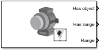
Simulation 3D Ultrasonic Sensor
Libraries:
Automated Driving Toolbox /
Simulation 3D
Aerospace Blockset /
Animation /
Simulation 3D
UAV Toolbox /
Simulation 3D
Simulink 3D Animation /
Simulation 3D /
Sensors
Description
The Simulation 3D Ultrasonic Sensor block generates detections from range measurements taken by an ultrasonic sensor mounted on an ego vehicle in a 3D simulation environment rendered using the Unreal Engine® from Epic Games®. The block calculates range measurements based on the distance between the sensor and the closest point on the detected object.
If you set Sample time to -1, the block uses the
sample time specified in the Simulation 3D Scene Configuration block. To use
this sensor, you must include a Simulation 3D Scene Configuration block in your
model.
Tip
The Simulation 3D Scene Configuration
block must execute before the Simulation 3D Ultrasonic Sensor block. That
way, the Unreal Engine 3D visualization environment prepares the data before the Simulation 3D
Ultrasonic Sensor block receives it. To check the block execution order,
right-click the blocks and then click the Properties button ![]() . On the General tab, confirm these
Priority settings:
. On the General tab, confirm these
Priority settings:
Simulation 3D Scene Configuration —
0Simulation 3D Ultrasonic Sensor —
1
For more information about execution order, see Control and Display Execution Order (Simulink).
The Coordinate system parameter of the block specifies how the actor transformations are applied in the 3D environment. The output of the block also follows the specified coordinate system.