Disable PID Autotuning in Presence of Downstream Signal Limiting
This example shows how to disable PID autotuning when the values of downstream signals are limited. The Closed-Loop PID Autotuner block in Simulink® Control Design™ perturbs the plant to obtain the frequency response estimate at five discrete frequencies. After obtaining the frequency response estimate, the block calculates the PID gains and outputs them for use in the upstream PID controller. However, when the plant response is limited, the accuracy of the frequency response estimate cannot be guaranteed, and the calculated PID gains may not be valid. This example demonstrates how you can stop the frequency response estimation process and prevent the PID gains from updating when the system encounters limitations.
Model Overview
This example uses the model from the Motor Control Blockset™ example Field-Oriented Control of PMSM Using Quadrature Encoder (Motor Control Blockset) as its baseline. The model is specifically modified to facilitate PI autotuning for the Q-axis current controller.
Open the model.
scdStopTuningWithInportInit
             model: 'Anaheim-BLY171D-24V-4000'
                sn: '001'
                 p: 4
                Rs: 0.7500
                Ld: 0.0010
                Lq: 0.0010
                 J: 2.4019e-06
                 B: 1.1604e-05
                Ke: 3.8000
                Kt: 0.0340
           I_rated: 1.8000
             N_max: 10000
    PositionOffset: 0.1700
          QEPSlits: 1250
            FluxPM: 0.0052
           T_rated: 0.0566
            N_base: 5298

                   model: 'DRV8312-C2-KIT'
                      sn: 'INV_XXXX'
                    V_dc: 24
                  I_trip: 9.7000
                  Rds_on: 0.0800
                  Rshunt: 0.0100
           CtSensAOffset: 2052
           CtSensBOffset: 2043
                 ADCGain: 1
             EnableLogic: 1
            invertingAmp: -1
              ISenseVref: 3.3000
        ISenseVoltPerAmp: 0.1908
               ISenseMax: 8.6478
                 R_board: 0.0833
         CtSensOffsetMax: 2500
         CtSensOffsetMin: 1500
    ADCOffsetCalibEnable: 1

                 model: 'LAUNCHXL-F28069M'
                    sn: '123456'
         CPU_frequency: 90000000
         PWM_frequency: 20000
    PWM_Counter_Period: 2250
              ADC_Vref: 3.3000
          ADC_MaxCount: 4095
         SCI_baud_rate: 5625000
               comport: '<Select a port...>'

    V_base: 13.8564
    I_base: 8.6478
    N_base: 5298
    P_base: 179.7411
    T_base: 0.2718
mdl = "scdStopTuningWithInport";
open_system(mdl)
Autotuning the Q Axis Current Controller
In the original model, the direct (D) and quadrature (Q) axis voltages output from the current controllers are limited by the DQ Limiter (Motor Control Blockset) block such that their combined magnitude vector is less than 0.95 per unit. In this example, you add the Closed-Loop PID Autotuner to the Q axis loop to tune the PI gains, which requires injecting perturbations into the plant before the limiter. The example uses the isExpGood optional inport of the Closed-Loop PID Autotuner block to ensure that if the system is limiting, the perturbations are stopped and the PI gains are not tuned.
Adding PID Autotuning for Q Axis Current Controller
In this example, the Closed-Loop PID Autotuner block tunes only the Q-axis current loop. The first part of the tuning process involves perturbing the output of the PI controllers to obtain a frequency response estimate of the plant at five frequencies. Once this estimate is obtained, it is used to calculate the PI controller gains at the block output. During the experiment phase of autotuning, it is crucial that the PI controller output and the perturbations are not limited, as the Closed-Loop PID Autotuner block assumes its perturbations are unrestricted when estimating the frequency response. The following figure shows the updated Q-axis PI controller subsystem with the Closed-Loop PID Autotuner added.
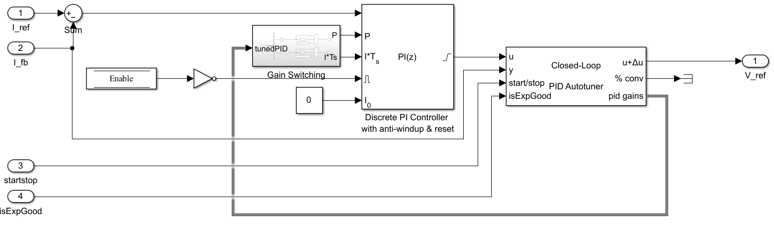
The Closed-Loop PID Autotuner is connected to the output of the PI Controller, and the tuned gains are fed back for use. The Gain Switching subsystem uses the default gains until the autotuner completes the tuning process.
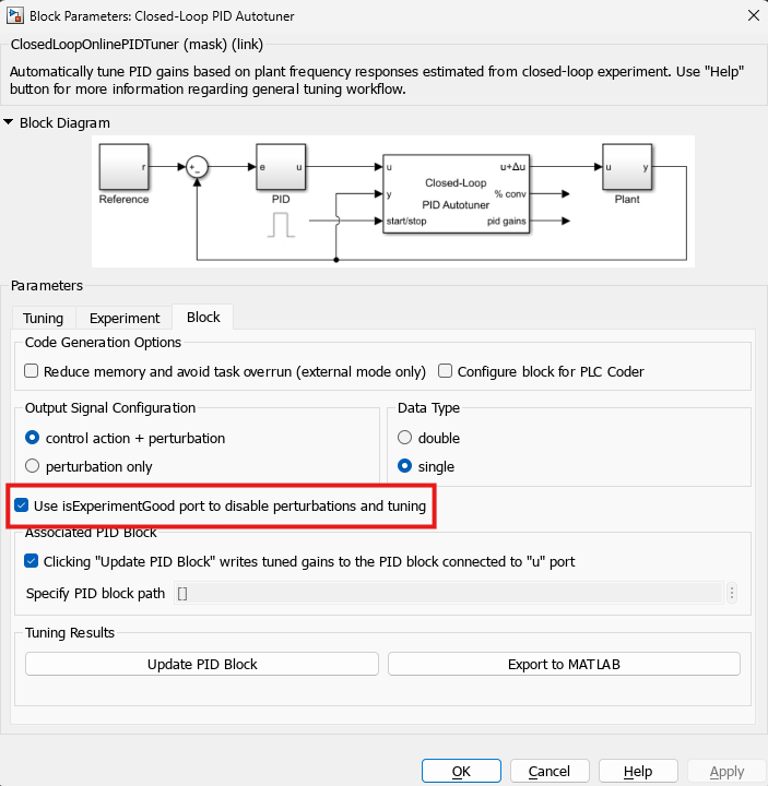
Use isExpGood Port to Disable Autotuning
To enable the isExpGood port, select Use isExperimentGood port to disable perturbations and tuning on the Block tab. When you provide a value of 1 (true) at this input, the Closed-Loop PID Autotuner block outputs experiment (perturbations) as normal. If the value is 0 (false), the block sets the perturbations to zero and does not perform tuning. In order to allow perturbations and tuning again, you must first set the start/stop signal to 0 then set back to 1 and start a new experiment. The isExpGood port latches whenever its value is false until a new experiment is triggered.
DQ Limiting
As mentioned previously, the DQ Limiter used in the current control system limits the voltage reference signals output from the current loop PI controllers, including the perturbations from the Closed-Loop PID Autotuner block. This limiter ensures that the magnitude of the D-axis and Q-axis currents remains below a defined per unit value, set to 0.95 in this case. If this limit is exceeded, the D-axis and Q-axis voltage references are adjusted to remain within the per unit limit. When this limiting occurs, the frequency response estimation by Closed-Loop PID Autotuner may be poor, resulting in improperly tuned PI gains. To ensure the validity of the tuned PI gains, you can use the isExpGood inport of the Closed-Loop PID Autotuner to stop the experiment perturbations and prevent updating the PID gains. In this example, you compare the magnitude output of the DQ Limiter block to the per unit limit value to determine if limiting occurs. If the per unit value is below the threshold, the experiment is considered valid and allowed to proceed normally.
Autotuning While Limiting
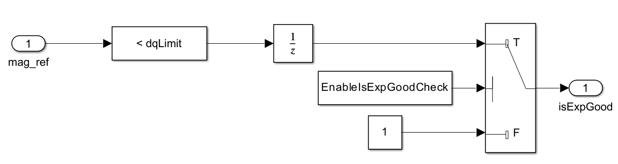
As discussed earlier, to obtain acceptable PID gains from Closed-Loop PID Autotuner, a good frequency response estimate is necessary. To prevent system limiting from causing poorly tuned gains and undesirable system performance, you can use the isExpGood inport as a safeguard. The following figure shows the logic used to determine if the experiment is valid. This logic checks if the magnitude reference output from the DQ Limiter block is below the defined limit (by default this is 0.95).
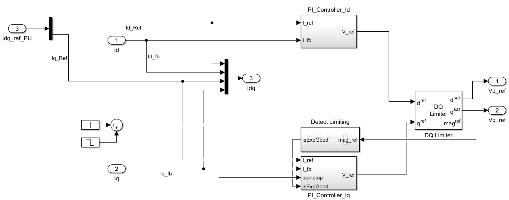
The following figure shows the Current Controllers subsystem that contains the D-axis and Q-axis controllers, the DQ limiter, and the block to detect if limiting is occurring.
Simulation Results with the isExpGood Inport
Simulate the model and save the results.
sim(mdl)
baselineResults = logsout;
For this example, the system is commanded to a speed of 0.2 per unit (PU) at the start of the simulation then 0.8 PU at 0.5 seconds. Autotuning occurs from 1 to 1.25 seconds and, at 1.5 seconds, the speed is commanded from 0.8 PU to -0.8. The baseline setup for this example has the DQ limit set to 0.95 PU with the detect limiting functionality enabled.
Plot baseline speed response.
figure
plot(baselineResults{11}.Values)
hold on
plot(baselineResults{10}.Values)
hold off
legend("Speed Command", "Speed Feedback",Location="southwest")
For reference below are the gains that result from the tuning process when no limiting is occurring:
Kp = 5.982
Ki = 4804
Next, repeat the same simulation but set the DQ limit to 0.82 in order to cause the system to limit during the autotuning process. The isExpGood port stops the experiment and not tune the gains in this case.
% Set DQ Limit to 0.83 per unit
dqLimit = 0.83;
% Simulate the model and save results
sim(mdl)
lowDQlimitResults = logsout;

% Plot comparison of DQ currents against baseline
figure
plot(baselineResults{5}.Values)
hold on
plot(lowDQlimitResults{5}.Values)
hold off
legend("Baseline","Low DQ Limit")

As shown in the response, when the DQ limiter is active in the second simulation (red trace), the block disables perturbations into the system. Normally, when the start/stop signal has a falling edge, the block tunes and updates the PI gains. However, because the isExpGood port is false during the experiment, the block does not tune the gains and preserves the system performance prior to tuning. You can see this in the speed reversal that occurs at 1.5 seconds. During this transient, the tuned result (blue trace) has a lower settling time, less overshoot, and oscillation compared to the undertuned case in the 2nd simulation.
The final simulation in this example disables the DQ limiting functionality and allows the PI gains to be tuned even though the system is limiting.
% Disable the use of the isExpGood port
EnableIsExpGoodCheck = false;
% Simulate the model and save results
sim(mdl)
disablePortResults = logsout;

% Plot comparison of DQ currents against baseline
figure
plot(baselineResults{5}.Values)
hold on
plot(lowDQlimitResults{5}.Values)
plot(disablePortResults{5}.Values)
hold off
legend("Baseline","Low DQ Limit","Low DQ Limit Tuned",Location="southwest")
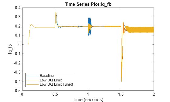
In the baseline simulation, the tuned gains are 5.982 and 4804 for the proportional and integral gains, respectively. The same gains obtained while the system is limited are 20.97 and 1833. By comparing these two sets of gains, it is clear that the tuned gains during limiting are compromised.
As shown, the tuned gains that result from a poorly estimated plant cause the tuned PI gains to be inaccurate. This results in the currents having large oscillations during steady-state and poor performance during the speed reversal transient. In this case, it is better to keep the original gains than to use the tuned gains that result from tuning while the DQ limiter is active.
Summary
In this example, the optional inport isExpGood on the Closed-Loop PID Autotuner is used to disable tuning when the system is limiting. When the isExpGood port is used, the Closed-Loop Autotuner block stops the perturbations and disables tuning the PID gains until a new experiment is started. Using this inport protects the system from going unstable due to the perturbations and from tuning gains from an improperly estimated plant.