Creating and Using Coverage Filters
This example shows how to use coverage filters to exclude model elements from coverage analysis and justify missing coverage in reports.
Coverage Filters
During the verification process, a model can contain several constructs that prevent full model coverage, such as a subsystem that contains a driver for a controller that is not tested and is not relevant to the validation process. You can exclude this subsystem from the coverage results.
Alternatively, you may have testing criteria that requires exercising certain aspects of a block, such as hitting particular decision points. If it is not feasible to satisfy all coverage outcomes for this block, and you did not intend for your tests to exercise these unsatisfied outcomes, then you can justify the missing coverage.
Filtering these constructs in coverage results by excluding or justifying them allows you to focus on other aspects of missing coverage that can and should be tested.
Coverage filters are stored in CVF files. Each filter consists of rules that exclude or justify certain model objects or individual coverage objective outcomes. You can apply multiple filter files to coverage results for a model. Multiple models can also use the same filter file.
You can create and apply coverage filters either before or after simulating a model.
Open Model
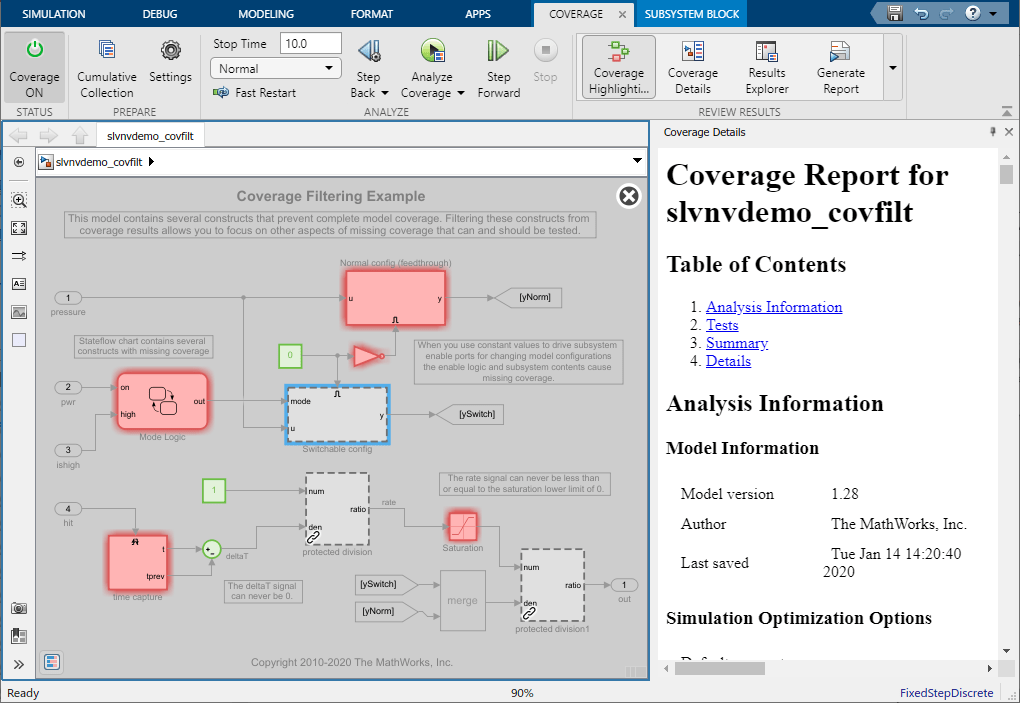
This example uses the slvnvdemo_covfilt model, which contains several constructs that prevent complete model coverage. Filtering these constructs from coverage results allows you to focus on more relevant aspects of missing coverage for the tests you are running.
open_system('slvnvdemo_covfilt');
Specify Items to Exclude from Coverage Results Before Simulation
The library block slvnvdemo_covfilt_lib/protected division protects against division by zero. If you determine that your testing is not expected or intended to fully cover every instance of this block in this context, you can exclude this block from the coverage results.
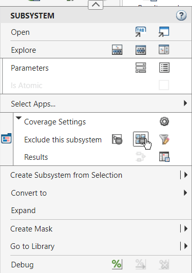
To change coverage settings from the context menu, you must first open the Coverage Analyzer app. On the Apps tab, click Coverage Analyzer. In the model, right-click the protected division library block and click Exclude referenced library: slvnvdemo_covfilt_lib/protected division to filter all references to the library. Each button in the context menu has a tooltip that describes what it does.
The Filter Editor pane of the Coverage Results Explorer opens. The Coverage Results Explorer creates a new filter file named Untitled by default and added a filter rule that excludes all references to the library block.
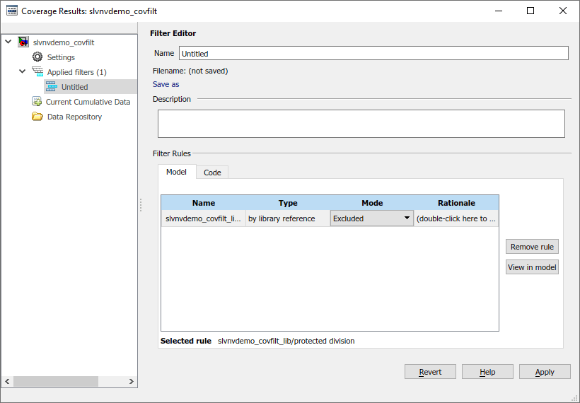
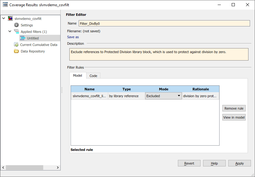
Specify a name and description for the new filter file by using the Name and Description fields. In the table, double-click the Rationale field for the new rule and enter text describing why this block is excluded, such as division by zero protection. Click Apply to save the filter file. A file dialog prompts you to specify where to save this file.
Reuse Existing Filter File
If you have models that contains similar constructs, you can use a filter file in multiple models.
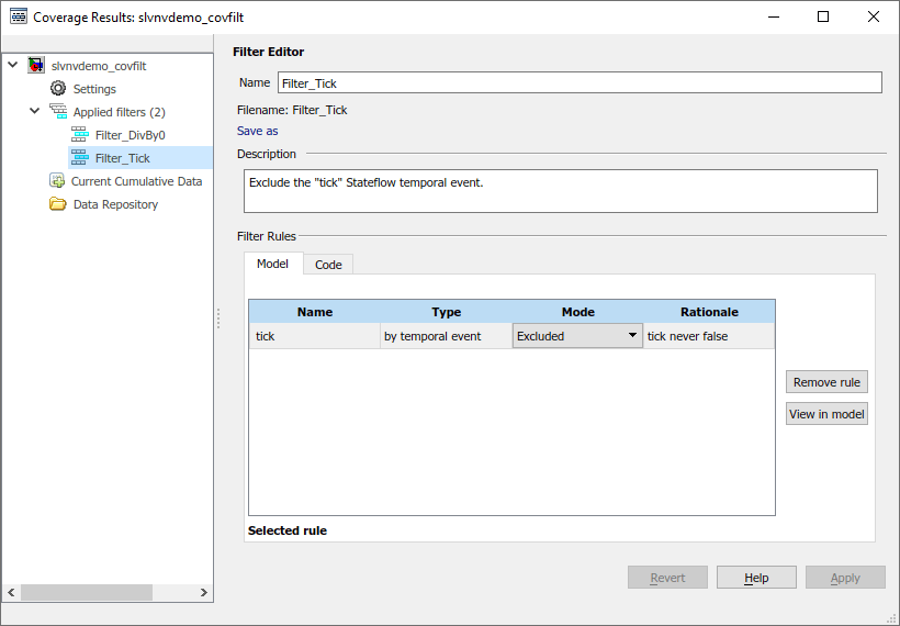
For example, the filter file Filter_Tick.cvf excludes the Stateflow® temporal event tick from coverage results. This event cannot be false and prevents full condition and MCDC coverage in any model using tick in event-based temporal logic in Stateflow.
Because slvnvdemo_covfilt/Mode Logic contains this construct, you can apply the filter file Filter_Tick.cvf to the model.
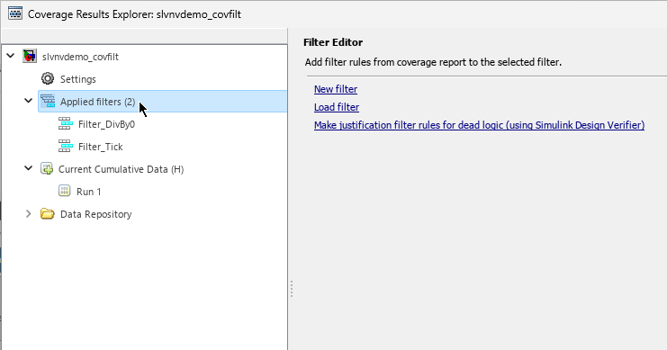
To apply this existing filter file, right-click the Applied filters node in the Coverage Results Explorer and select Load filter. In the file dialog, select Filter_Tick.cvf and click Open.
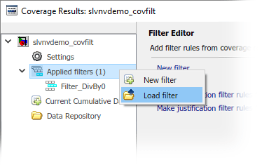
Note that Applied filters now lists both Filter_DivBy0 and Filter_Tick.
Simulate and Review Filtered Coverage Results
Click the Run (Coverage) button to simulate the model and record coverage. When the simulation completes, Simulink® Coverage™ highlights the model with the coverage results and the Coverage Details pane opens.
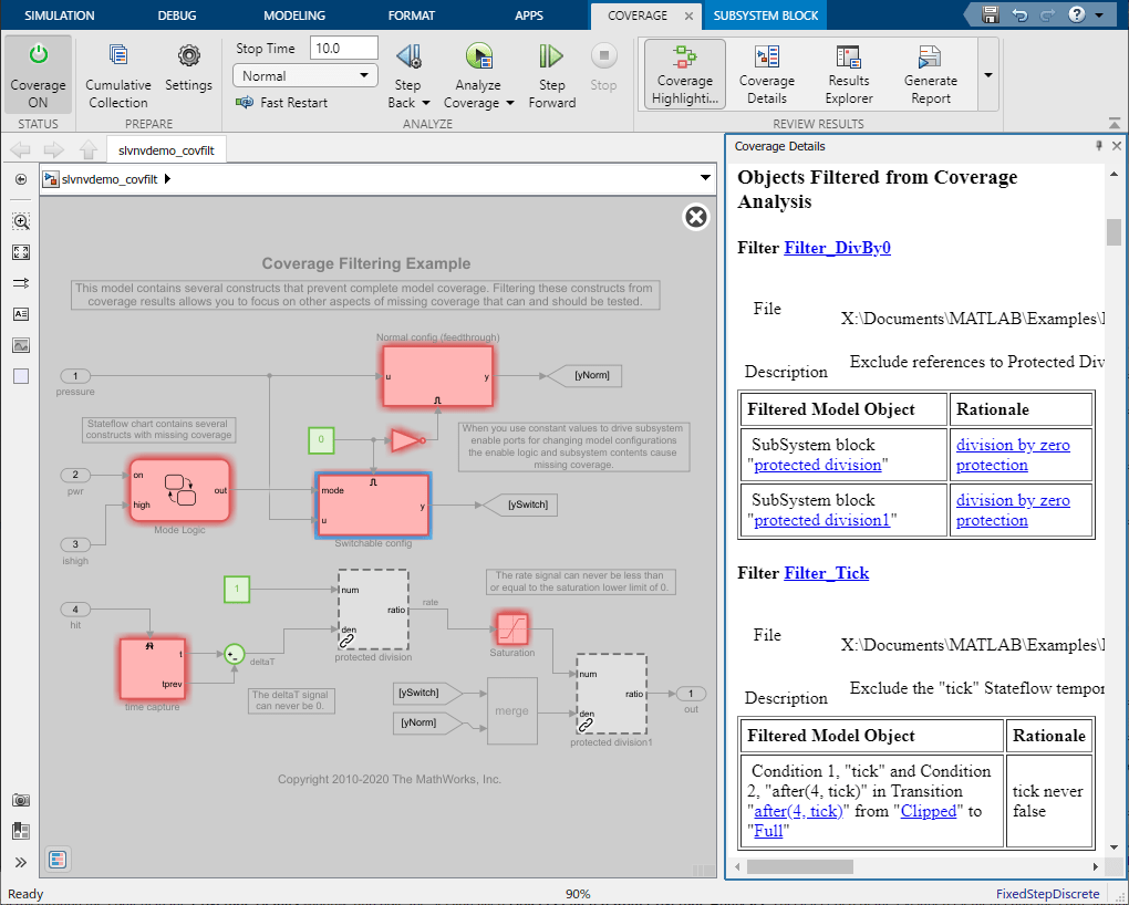
Both references to the protected division library block are gray with a dashed border, which indicates that Simulink Coverage did not analyze them due to the exclusion rule.
In the Coverage Details pane, the Objects Filtered from Coverage Analysis section lists each of the excluded elements and the corresponding rationales for each. Both Filter_DivBy0 and Filter_Tick appear here.
Create a New Filter File
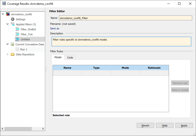
Create another filter file to capture filter rules exclusively relevant to this model.
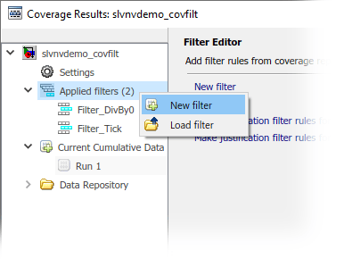
In the Coverage Results Explorer, right-click the Applied filters node and select New filter.
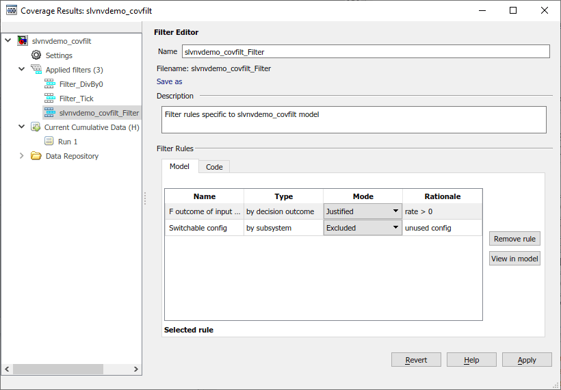
Enter a name and description for this filter file. For this example, set the name to slvnvdemo_covfilt_Filter, and set the description to Filter rules specific to slvnvdemo_covfilt model. Click Apply and specify where to save the file.
Exclude Items from Coverage Results After Simulation
You can also create and apply filter rules to coverage results after simulation. This allows you to review coverage results, create or adjust filters, and generate a new coverage report without having to rerun the simulation.
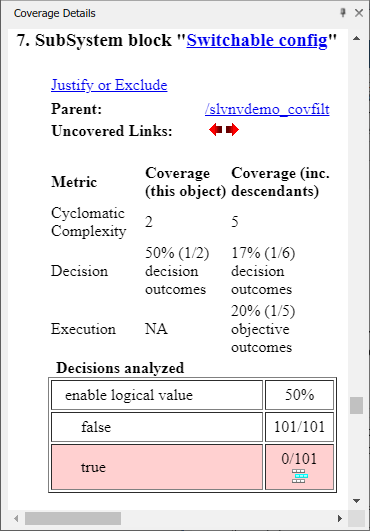
For example, consider the Switchable config subsystem, which models a common design pattern that uses constant values to drive subsystem enable ports to change model configurations. However, the enable logic and subsystem contents might lead to missing coverage. Because this model does not use this configuration, you can exclude it from coverage analysis.
When you add a new filter rule from the Coverage Details pane, Simulink Coverage adds the new filter rule to whichever filter file you currently have selected. To create a new filter rule, then first click Applied filters.
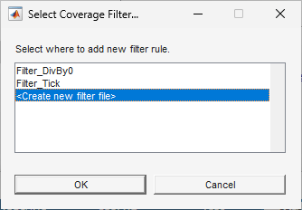
In the Simulink Editor, click the Switchable config subsystem. The Coverage Details pane displays the coverage details for this subsystem. Click the Justify or Exclude link. The Select Coverage Filter dialog box opens, click <Create new filter file>.
Enter a name and description for the new filter file. In the Filter Rules section, enter a rationale for this rule, such as unused config.
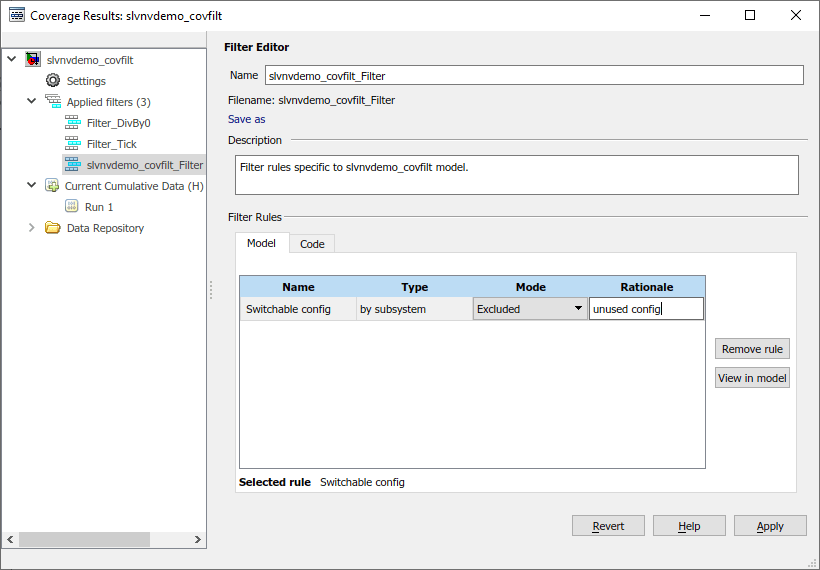
Click Apply to save the changes to the filter file and update the coverage results.
The Switchable config subsystem is now gray with a dashed border, instead of red with a solid border, which indicates that the filter excluded it from the coverage results.
Justify Individual Objective Outcomes from the Coverage Results
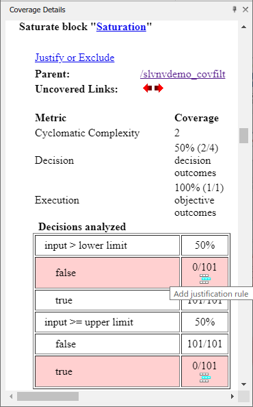
In the Simulink Editor, click the Saturation block named Saturation and review the coverage results in the Coverage Details pane. Two decision outcomes are unsatisfied because the Saturation block has a lower limit of 0 and an upper limit of 200. However, the input to this block is the rate signal, which can never be less than or equal to 0. As such, the lower limit of the Saturation block is not fully exercised, so you can justify the corresponding decision outcome.
Next to the false outcome for the decision input > lower limit, click the Add justification rule icon ![]() .
.
The Coverage Results Explorer adds a new filter rule to the currently selected filter file in the Filter Editor pane. Specify a justification rationale, such as rate > 0.
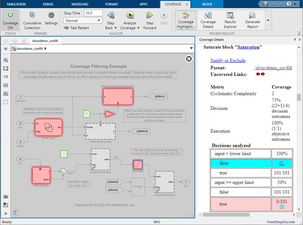
Click Apply to save the filter file and update the coverage results.
Note that, in the Coverage Details pane, the justified outcome of the Saturation block is light blue and links to the rationale. Because you did not filter the true outcome of the decision input >= upper limit and the analysis is insufficient to exercise this outcome, the Saturation block still has missing coverage and stays red.
Use Simulink Design Verifier to Generate Filter Rules for Dead Logic
In some cases, missing coverage is due to dead logic and the associated coverage objectives are unsatisfiable. If this logic is meant for elements that you do not wish to remove from your model, then you can justify these missing coverage outcomes.
If you have a Simulink Design Verifier™ license, you can automatically create justification filter rules for dead logic.
In the Coverage Results Explorer, select the Applied filters node. In the Filter Editor pane, select Make justification filter rules for dead logic (using Simulink Design Verifier).
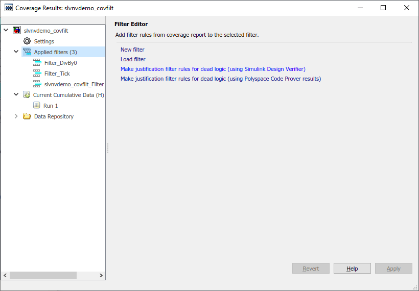
This option uses Simulink Design Verifier™ to analyze the model for dead logic. Simulink Design Verifier creates a new filter and adds justification rules for each of the corresponding coverage outcomes.
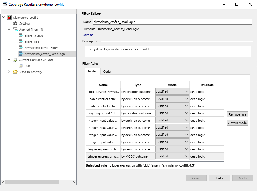
Simulink Design Verifier detects and justifies dead logic for two condition outcomes, seven decision outcomes, and one MCDC outcome.
Specify a name and description for this filter file. For this example, set the name to slvnvdemo_covfilt_DeadLogic, and set the description to Justify dead logic in slvnvdemo_covfilt model, then click Apply. In the file dialog, specify where to save this filter file.
Close the Simulink Design Verifier Results windows.
In R2026a, you can also initiate the dead logic detection analysis from the coverage report. For more information, see Identify and Resolve Missing Coverage Caused by Dead Logic.
Review Filtered Coverage Results
In the Simulink Editor, in the Coverage tab, in the Review Results section, select Coverage Highlighting.
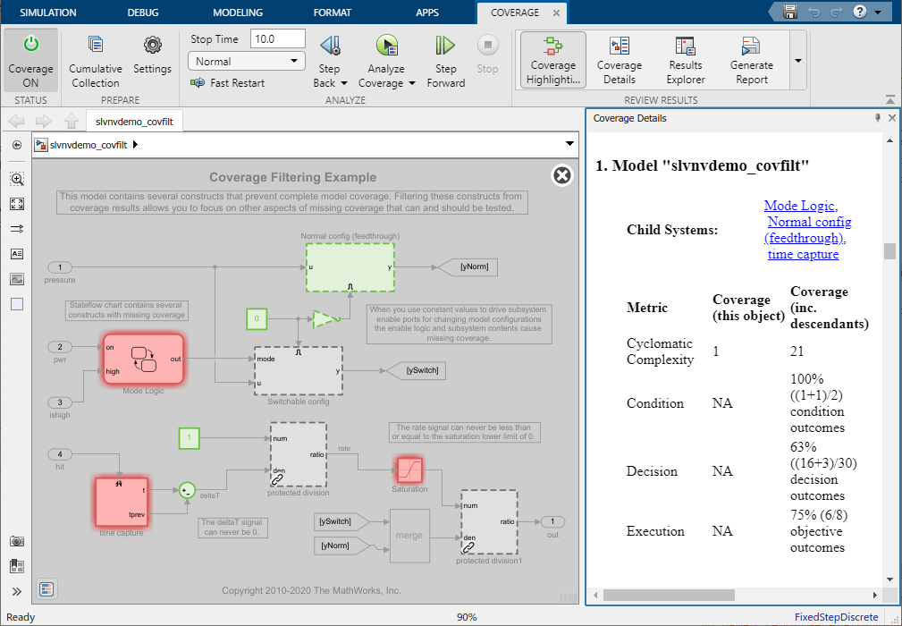
After applying the four filters in this example, the simulation now achieves 100% condition, 63% decision, and 75% execution coverage for this model. The coverage results no longer contain model objects that receive MCDC, so the coverage report does not list this metric. The coverage report does not display the MCDC outcome that the dead logic analysis filters out because the coverage filter Filter_Tick contains an exclusion rule that eliminates that outcome from the report.
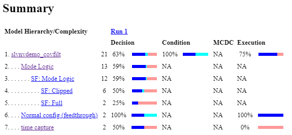
The remaining missing coverage in the Mode Logic chart, time capture subsystem, and Saturation block indicates inadequate testing. You can address unresolved coverage of this type by extending your testing to more thoroughly exercise these model elements.
See Also
slcoverage.Filter | slcoverage.FilterRule