Review Design Error Detection Analysis Results
When the design error detection analysis is complete:
Simulink® Design Verifier™ highlights the model with the analysis results.
The Simulink Design Verifier Results Summary window opens and displays a summary of the analysis.
Highlight Analysis Results on Model
After the design error detection analysis is complete, the results are highlighted automatically in the model sldvexDetectDesignErrorsExample.
1. Select the Sum block. The Results window displays the integer overflow objectives of the Sum block.
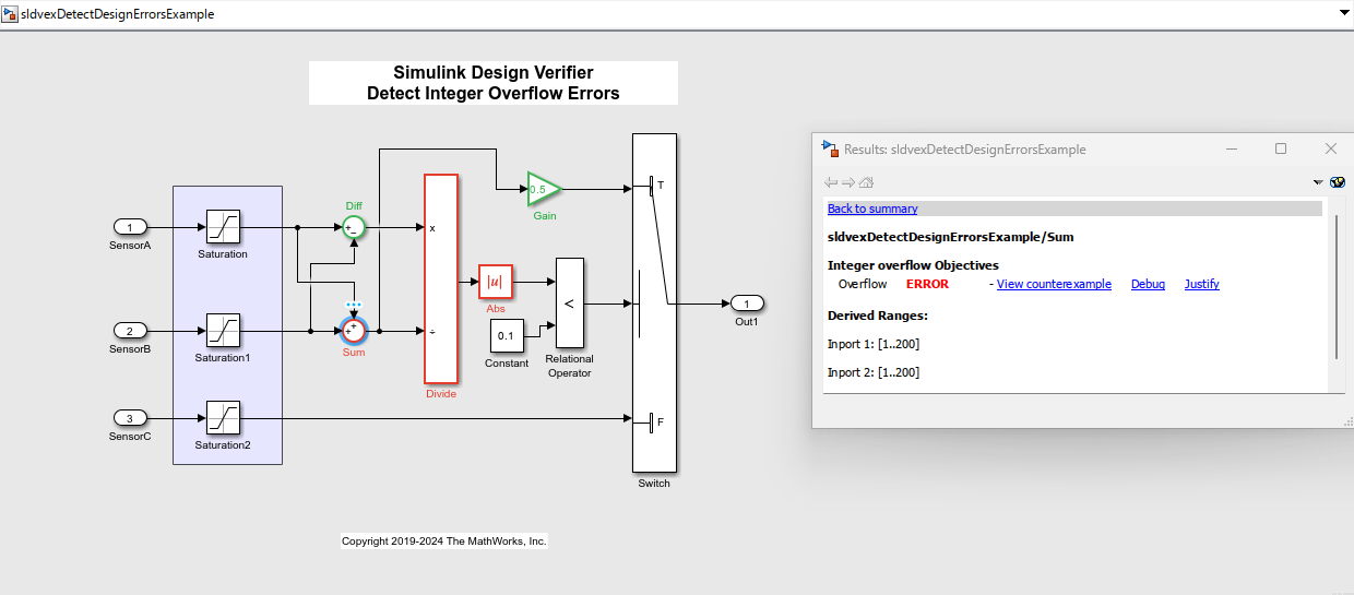
2. To debug the integer overflow error, click View counterexample. The harness model sldvexDetectDesignErrorsExample_harness and the Block Parameters dialog box of the Inputs block opens.
3. In the Block Parameters dialog box, from the Active scenario list, select Counterexample_3. Click Apply.
The Input block in the harness model indicates Counterexample_3 as the active scenario.

4. Double-click the Inputs block to open the Block Parameters dialog box.
5. In the Block Parameters dialog box, click the Open Signal Editor button from ![]() to visualize the scenarios.
to visualize the scenarios.

When the input value of CounterExample_3.SensorA is 96 and the input value of CounterExample_3.SensorB is 160, the Sum block output overflows. The accumulator data type of the Sum block is set to an incorrect type uint8, which results in overflow errors and division-by-zero errors on the downstream Divide block.
Review Design Error Detection Analysis Report
To view the HTML Design Error Detection Analysis Report, in the Results Summary window, click HTML. The HTML report opens in the MATLAB® Editor. The Design Error Detection Objectives section of the report lists the objectives of each model item and their description.
The analysis report shows that three objectives are valid and three objectives are falsified with counterexamples.
