Derived Ranges in Design Error Detection
When you specify minimum and maximum values for a signal or data in a model, these values define a design range. Use the Output minimum and Output maximum parameters of a block to specify a range of valid values for the block output signal. For more information, see Specify Signal Ranges.
Simulink® Design Verifier™ analyzes model behavior and computes the values that can occur during simulation for block outports and Stateflow® local data. The ranges of these values are called derived ranges. For more information, see Derive Ranges (Fixed-Point Designer).
You can use derived ranges in Simulink Design Verifier analysis to compute ranges of intermediate signals. Simulink Design Verifier allows you to add minimum or maximum values at the model inport. When Use specified input minimum and maximum values is selected, derived range computation involves propagation of specified design ranges on model inports to compute ranges of the intermediate signals. Design ranges are user specified minimum and maximum values on signals and data elements within a model such as Inport and Outport blocks, block outputs, model elements in MATLAB Function blocks and Stateflow data. For more information, see Work with Signal Ranges in Blocks.
How Analysis Uses Input Constraints
During design error detection analysis, Use specified input minimum and maximum values is selected by default. The analysis uses the design ranges on the model input ports as constraints to calculate the derived ranges.
If Use specified input minimum and maximum values is cleared, the tool does not restrict the signal ranges when computing the derived ranges.
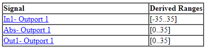
Consider this model where the design ranges are [–35..35] for the
Inport block output.
![]()
On Design Verifier tab, select Design Error Detection and then, click Detect Design Errors to run the analysis.
With the input range of [–35..35] specified on the Inport
block, the only possible values for the Abs block output are from
0 to 35.
If you configure [0..30] as design range, derived ranges computation in
the analysis report indicates [0..35] and thus it is useful to
compute derived ranges when your model undergoes changes.
However, if you clear Use specified input minimum and maximum
values, the analysis calculates the derived ranges based on unrestricted
values of the input ports of the model. In this model, the only possible outputs of
the Abs block are nonnegative numbers. The derived range for the
Abs block is [0..inf] when design range is not
specified for the Inport block.
How to Access Derived Ranges
You can access derived ranges from:
Design error detection analysis data file. Access signal ranges under
sldvDatastructure fromsldvData.Objectives.rangeAnalysis report and the Results Summary window
How Analysis Calculates Derived Ranges
The analysis behavior changes based on the value of Use specified input minimum and maximum values:
| Setting | Derived range calculation |
|---|---|
on | Simulink Design Verifier uses the design range specified for input signals in a model. The specified input signals range affects the derived ranges of downstream signals in the model. |
off | Simulink Design Verifier uses the full data type range for input signals. |
For derived range calculations, Simulink Design Verifier ignores design ranges for intermediate signals, regardless of the Use specified input minimum and maximum values parameter setting.
The derived ranges that Simulink Design Verifier analysis computes are approximate and may not be exact.
Simulink
Design Verifier analysis does not compute derived ranges on output ports with data
type set to enumeration.
Use of Derived Ranges
Design range is a subset of derived range. To improve the precision of the calculated range, specify the design range on the model inports. If the model involves internal loops, time varying behavior of the computed range is wider than the actual design range.
Analyzing derived ranges allows you analyze dead logic and justify the dead objectives based on the calculated ranges. For example, if the derived range of the output of a logic block is always
false, then it justifies the dead logic in Condition and MCDC model coverage objectives for the block.You can check the precision of specified ranges by computing derived ranges if you have a precomputed design ranges for intermediate signals. Alternatively, select the model configuration parameter Use specified input minimum and maximum values to verify if the ranges are accurate.
See Also
Derive Ranges Using Design Ranges (Fixed-Point Designer)