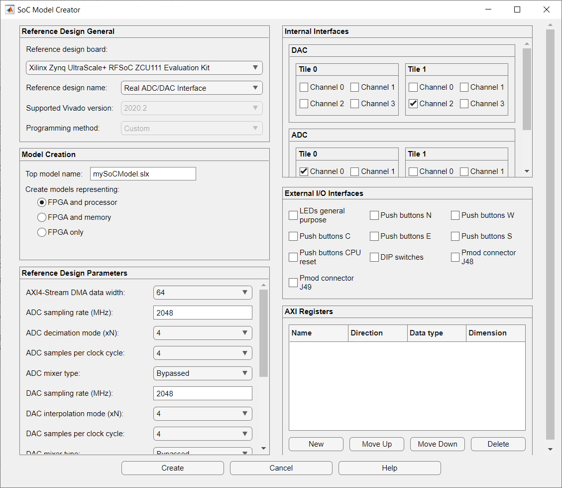
SoC Model Creator
Create SoC model based on selected reference design
Since R2021b
Description
The SoC Model Creator tool enables you to create an SoC model that is compatible with a selected reference design. Use this tool to select a reference design and configure its parameters before you create an SoC model. The created model has a subsystem that adheres to the interfaces as per your selection. You can add an algorithm in the subsystem in the created model for simulation, HDL code generation, and SoC deployment.
Note
The SoC Model Creator tool replaces the removed SoC Template Builder tool. For more information, see Version History.
The SoC Model Creator tool enables you to choose the reference design for which you want to create an SoC model. The tool also enables you to select the type of model and customize the model by using the reference design parameters, predefined internal interfaces, external input/output (I/O) interfaces, and AXI registers. Use the SoC Model Creator to perform these actions.
Create an SoC model with the required I/O blocks connected.
Configure the SoC model with the selected board and reference design.
Set the target interface for the SoC model input and output.
Edit the created model to include the required algorithm. Navigate to the blocks FPGA Algorithm in the FPGA model or Processor Algorithm in the processor model. Replace these blocks with your own algorithm model. Then, simulate the system and use the SoC Builder tool to build software executables and an FPGA programming file from your model and program the target hardware board.
Open the SoC Model Creator
MATLAB® command prompt: Enter
socModelCreator.
Examples
Limitations
Use this tool only when targeting the Xilinx® Zynq® UltraScale+™ or Xilinx Versal® ACAP devices.
