Target an ARM Processor on Zynq Hardware
Workflow Overview
This support package helps you design an algorithm targeted for the ARM® processor on the Zynq® board. Use this support package and Simulink® targeting tools to deploy the algorithm to the hardware and run it in external mode or full deployment. Your algorithm can interact with the design loaded to the FPGA through AXI-Lite registers and by routing the video data to the ARM processor.
Create a model for software targeting using the default FPGA design loaded at setup, or customize the FPGA logic and use the generated software interface model. In either case, you can use the Video Capture blocks to route the video from the FPGA into the ARM processor, and to control the data path in the FPGA.
Required Products
To generate and deploy code to the ARM processor, these products are required:
Embedded Coder®
Embedded Coder Support Package for AMD SoC Devices
Tunable Parameters
During simulation, you can adjust the following parameters:
Bypass FPGA user logic on the Video Capture HDMI block
Any control ports in the FPGA user logic
Step 1. Create a Model
You can create a model for software targeting using the default FPGA design loaded at setup. You can also customize the FPGA logic and use targeted software to interface with your FPGA design (see Models Generated from FPGA Targeting). If you have an HDMI FMC card, use the Video Capture HDMI block to route the video data into the ARM processor. If you have a MIPI® FMC card, use the Video Capture MIPI block.
When you use the default FPGA design, you can change the video parameters on the block to configure the format of the imported frames. In the generated software interface model, the pixel format parameters are locked to match the video format in the FPGA. The generated model also includes a Xilinx Zynq AXI Interface block, with ports to read and write the AXI-Lite registers on the FPGA.
To view the modified video in Simulink, use the Video Viewer block in external mode.
Step 2. Check Setup
Make sure that the board is set up and the host computer is communicating with the hardware (see Set Up AMD FPGA and SoC Devices).
Make sure that you have run the setup steps in Setup for ARM Targeting with IP Core Generation Workflow.
Step 3. Configure Model
From the Tools menu, select Run on Target Hardware. Then, select either Prepare to Run or Options.
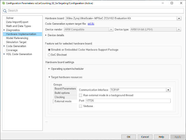
In the Configuration Parameters dialog box, select the Hardware Implementation pane.

For ZC702, ZC706, Zedboard, and PicoZed boards, set Hardware board to
Xilinx
                                    Zynq-7000 based board
. For ZCU102 or ZCU106 boards, set Hardware board toXilinx Zynq Ultrascale+ MPSoC ZCU102 Evaluation Kit.For ZCU102 or ZCU106 boards, the Feature set for selected hardware board section appears. Select Simulink or Embedded Coder Hardware Support Package.
For all boards, expand Target hardware resources > External mode and uncheck Run external mode in a background thread.
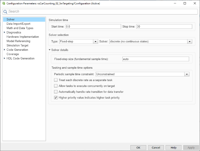
For all boards, open the Solver pane and uncheck Treat each discrete rate as a separate task.

Click OK.
Step 4. Run Algorithm on the ARM
To run your algorithm on the ARM processor, use one of these options:
External mode — Connect your Simulink model to your generated code running on the target processor and FPGA. The model becomes an interface to the real-time application. By changing parameters in the Simulink model, you also change parameters in the real-time application. In designs that use the generated software interface model, you can control AXI-Lite inputs to the FPGA user logic. With the Video Capture HDMI block, you can change the camera data source, and whether the FPGA user logic is enabled.
Full deployment — Run your generated code on standalone hardware, without a connection to Simulink.
Run in External Mode
In your model, set the simulation stop time to
Infto run the simulation until you explicitly pause or stop the model.If your model includes the Video Viewer block, to avoid buffering errors, reduce the duration of the external mode trigger. In the Code menu, select External Mode Control Panel. Click Signal & Triggering, then in the Trigger options section, set Duration to 1.
In the Simulink toolbar, set Simulation mode to
External. Then, click Run.The model is now running on the target hardware. You can see the messages coming from the model running on the target hardware in the Diagnostic Viewer.
Change any tunable parameters and observe the changes in the HDMI output from your hardware. See Tunable Parameters.
After observing the simulation, click Stop. The Diagnostic Viewer indicates that the model has stopped running. Close the viewer.
Run Model as Standalone Application
In the Simulink toolbar, click Deploy to Hardware ![]() .
.
The model is now running on the external hardware. The system command window that opens shows the messages coming from the model running on the target hardware. The video that is output from your board appears on your HDMI output. If your generated code included inputs from dip switches or push buttons on the board, use them to modify the operation of your system. Then observe the change in output.
Note
Deploying a new or updated model on the board:
Automatically stops a running model with the same name.
Does not stop running models that have other names.