Eddy Current
Eddy current loss representation
Libraries:
Simscape /
Electrical /
Passive
Description
The Eddy Current block models the effect of eddy currents by generating a magnetomotive force (MMF) that opposes changes in the magnetic flux. In addition, the block models parasitic effects using a series reluctance and a parallel leakage permeance, and thermal effects using an optional thermal port, H.
Eddy currents in magnetic core materials are caused by time-varying magnetic fields. These changing field densities induce voltage potentials within the material, causing current to flow in closed loops. Such currents are usually undesired and cause heating of the magnetic material.
Use this block to add eddy current losses in the magnetic domain to a custom transformer or other magnetic component.
The eddy current component is sometimes referred to as magnetic inductance because it is the magnetic-domain analog to an inductor in the electrical domain.
Equations
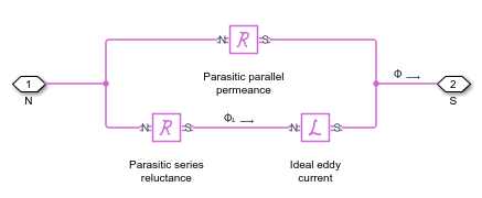
This is the equivalent magnetic circuit for the block, including the eddy current path (bottom) and parallel leakage path (top).

In the diagram:
is the total flux at the terminals. This flux is the summation of the eddy current loop and the parallel leakage path.
L is the flux through the eddy current loop.
The block calculates the terminal MMF, , and flux, , as:
where:
Geddy is the conductance of the eddy current loop.
is the parasitic series reluctance of the eddy current path.
is the parallel permeance.
Because the parasitic series reluctance and parallel permeance are lossless, the total dissipated power over the block is:
Relating Transformer Electrical and Magnetic Models
In the electrical domain, eddy current losses are modeled using a parallel resistance across the primary winding. This is the equivalent circuit for a nonideal two-winding transformer.

In the diagram:
Lp and Ls are the self-inductances of the primary and secondary windings, respectively.
Lm is the mutual inductance between the two windings.
Rm is the mutual resistance between the two windings, caused by the eddy current losses.
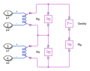
This two-winding transformer can similarly be represented in the magnetic domain. This is the equivalent circuit.

In the diagram:
p and s are the reluctances associated with the primary and secondary windings, respectively.
g is the reluctance associated with the magnetic coupling of the two windings.
n is the turns ratio between the two windings.
The electrical- and magnetic-domain circuits are equivalent if:
You can use these relationships to calculate the equivalent two-winding transformer properties for one domain from the other.
Examples
Ports
Conserving
Parameters
References
[1] Brown, A. D., J. N. Ross, and K. G. Nichols. "Time-domain simulation of mixed nonlinear magnetic and electronic systems." IEEE Transactions on Magnetics. Vol. 37, Number 1, 2001, pp. 522-532.
Extended Capabilities
Version History
Introduced in R2018a


