Main Content

Hall-Effect Rotary Encoder

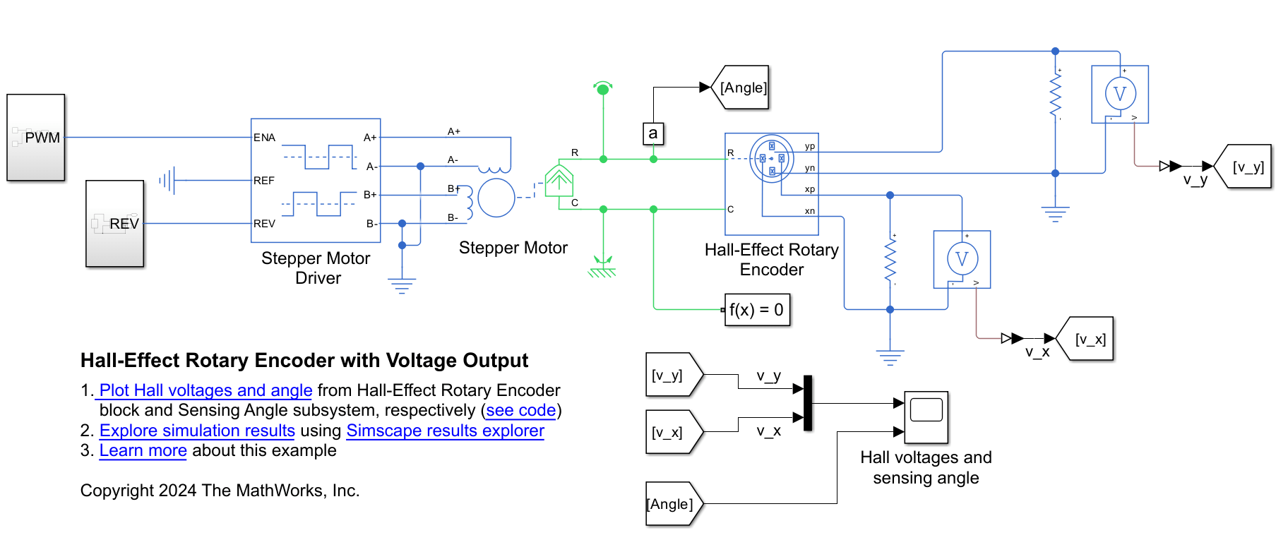
Four-element Hall-effect rotary encoder

Since R2019b

  • Hall-Effect Rotary Encoder block

Libraries:
Simscape / Electrical / Sensors & Transducers

Description

The Hall-Effect Rotary Encoder block models a 360° rotary position sensor using four Hall elements equally spaced under a magnetized, rotating magnet. The elements generate four sinusoidal waveforms.

Equations

The voltages between the elements of the rotary encoder are described by the equations:

vx=Vx0+Axcos(θ)

vy=Vy0+Aycos(θπ2+β),

where:

  • vx is the voltage between elements xp and xn;

  • vy is the voltage between elements yp and yn;

  • Ax and Ay are the voltage amplitudes for the x and y axes that reflect the sensitivity mismatch;

  • Vx0 and Vy0 are the voltage offsets for the x and y axes;

  • β is the quadrature error.

The block uses this equation to decode the angle:

θout=arctan(vyvx).

Variables

To set the priority and initial target values for the block variables before simulation, use the Initial Targets section in the block dialog box or Property Inspector. For more information, see Set Priority and Initial Target for Block Variables.

Nominal values provide a way to specify the expected magnitude of a variable in a model. Using system scaling based on nominal values increases the simulation robustness. You can specify nominal values using different sources, including the Nominal Values section in the block dialog box or Property Inspector. For more information, see System Scaling by Nominal Values.

Ports

Conserving

expand all

Mechanical rotational conserving port associated with the sensor positive probe.

Mechanical rotational conserving port associated with the sensor negative (reference) probe.

Electrical conserving port associated with the y-axis positive Hall field.

Dependencies

This port is visible only if you select Electrical connections for the Output interface parameter in the Parameters settings.

Electrical conserving port associated with the y-axis negative Hall field.

Dependencies

This port is visible only if you select Electrical connections for the Output interface parameter in the Parameters settings.

Electrical conserving port associated with the x-axis positive Hall field.

Dependencies

This port is visible only if you select Electrical connections for the Output interface parameter in the Parameters settings.

Electrical conserving port associated with the x-axis negative Hall field.

Dependencies

This port is visible only if you select Electrical connections for the Output interface parameter in the Parameters settings.

Output

expand all

Physical signal output port for the decoded position in terms of the rotational angle of the magnetic field in the x-y plane.

Dependencies

This port is visible only if you select Decoded angular position for the Output interface parameter in the Parameters settings.

Parameters

expand all

X-axis voltage amplitude, in V.

Y-axis voltage amplitude, in V.

Potential difference in the electric current flow through the electric conductor in the absence of external magnetic field on the x-axis, in V.

Potential difference in the electric current flow through the electric conductor in the absence of external magnetic field on the y-axis, in V.

Amount of quadrature error. Quadrature switching can decrease offset errors.

Port interface for decoded information.

Dependencies

The yp, yn, xp, and xn conserving ports are visible only if you select Electrical connections for the Output interface parameter.

The Angle physical signal port is visible only if you select Decoded angular position for the Output interface parameter.

Extended Capabilities

C/C++ Code Generation
Generate C and C++ code using Simulink® Coder™.

Version History

Introduced in R2019b