Main Content

Park to Clarke Angle Transform

Implement dq0 to αβ0 transform

  • Park to Clarke Angle Transform block

Libraries:
Simscape / Electrical / Control / Mathematical Transforms

Description

The Park to Clarke Angle Transform block converts the direct, quadrature, and zero components in a rotating reference frame to alpha, beta, and zero components in a stationary reference frame.

The block accepts the following inputs:

  • Either d-q axes components or multiplexed components dq0 in the rotating reference frame. Use the Number of inputs parameter to use either two or three inputs.

  • Sine and cosine values of the corresponding angles of transformation.

For balanced systems, the zero components are equal to zero.

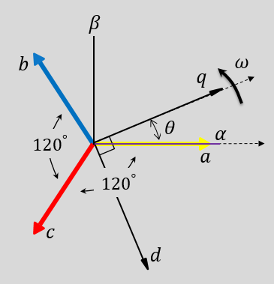
You can configure the block to align the phase a-axis of the three-phase system to either the q- or d-axis of the rotating reference frame at time, t = 0. The figures show the direction of the magnetic axes of the stator windings in the three-phase system, a stationary αβ0 reference frame, and a rotating dq0 reference frame where:

  • The a-axis and the q-axis are initially aligned.

  • The a-axis and the d-axis are initially aligned.

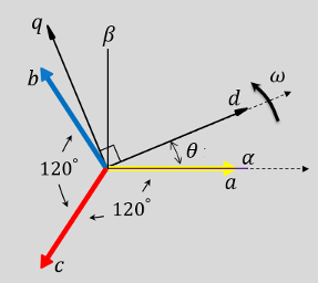
In both cases, the angle θ = ωt, where

  • θ is the angle between the a and q axes for the q-axis alignment or the angle between the a and d axes for the d-axis alignment.

  • ω is the rotational speed of the d-q reference frame.

  • t is the time, in s, from the initial alignment.

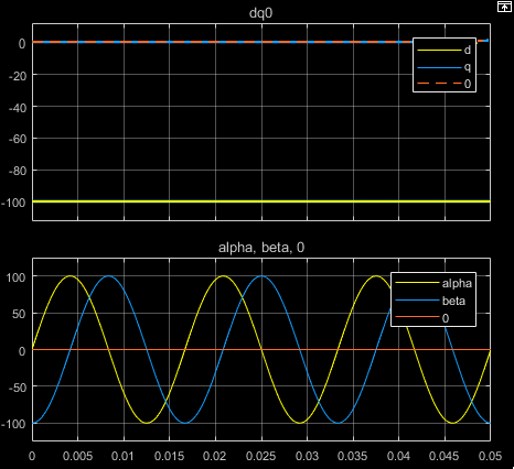
The figures show the time-response of the individual components of equivalent balanced dq0 and αβ0 for an:

  • Alignment of the a-phase vector to the q-axis

  • Alignment of the a-phase vector to the d-axis

Equations

The Park to Clarke Angle Transform block implements the transform for an a-phase to q-axis alignment as

[αβ0]=[sin(θ)cos(θ)0cos(θ)sin(θ)0001][dq0]

where:

  • d and q are the direct-axis and quadrature-axis components of the two-axis system in the rotating reference frame.

  • 0 is the zero component.

  • α and β are the alpha-axis and beta-axis components of the two-phase system in the stationary reference frame.

For an a-phase to d-axis alignment, the block implements the transform using this equation:

[αβ0]=[cos(θ)sin(θ)0sin(θ)cos(θ)0001][dq0]

Ports

Input

expand all

Direct-axis and quadrature-axis components and the zero component of the system in the rotating reference frame.

Dependencies

To enable this port, either clear the Use block for embedded implementation (requires Motor Control Blockset™) parameter or select the Use block for embedded implementation (requires Motor Control Blockset™) parameter and set Number of inputs to Three inputs. (since R2025a)

Data Types: single | double

Since R2025a

Direct-axis component, d, in the rotating dq reference frame.

Dependencies

To enable this port, select the Use block for embedded implementation (requires Motor Control Blockset™) parameter and set Number of inputs to Two inputs.

Data Types: single | double

Since R2025a

Quadrature-axis component, q, in the rotating dq reference frame.

Dependencies

To enable this port, select the Use block for embedded implementation (requires Motor Control Blockset™) parameter and set Number of inputs to Two inputs.

Data Types: single | double

Angular position of the rotating reference frame. The value of this parameter is equal to the polar distance from the vector of the a-phase in the abc reference frame to the initially aligned axis of the dq0 reference frame.

Dependencies

To enable this port, either clear the Use block for embedded implementation (requires Motor Control Blockset™) parameter or select the Use block for embedded implementation (requires Motor Control Blockset™) parameter and set Theta input to Electrical position. (since R2025a)

Data Types: single | double

Since R2025a

Sine value of the angle of transformation, θe. θe is the angle between the rotating reference frame and the α-axis.

Dependencies

To enable this port, select the Use block for embedded implementation (requires Motor Control Blockset™) parameter and set Theta input to Sine and Cosine electrical position.

Data Types: single | double

Since R2025a

Cosine value of the angle of transformation, θe. θe is the angle between the rotating reference frame and the α-axis.

Dependencies

To enable this port, select the Use block for embedded implementation (requires Motor Control Blockset™) parameter and set Theta input to Sine and Cosine electrical position.

Data Types: single | double

Output

expand all

Alpha-axis component,α, beta-axis component, β, and zero component of the two-phase system in the stationary reference frame.

Dependencies

To enable this port, either clear the Use block for embedded implementation (requires Motor Control Blockset™) parameter or select the Use block for embedded implementation (requires Motor Control Blockset™) parameter and set Number of inputs to Three inputs. (since R2025a)

Data Types: single | double

Since R2025a

Alpha-axis component,α, in the stationary reference frame.

Dependencies

To enable this port, select the Use block for embedded implementation (requires Motor Control Blockset™) parameter and set Number of inputs to Two inputs.

Data Types: single | double

Since R2025a

Beta-axis component,β, in the stationary reference frame.

Dependencies

To enable this port, select the Use block for embedded implementation (requires Motor Control Blockset™) parameter and set Number of inputs to Two inputs.

Data Types: single | double

Parameters

expand all

Align the a-phase vector of the abc reference frame to the d- or q-axis of the rotating reference frame.

Since R2025a

Option to use the block for embedded implementation. This option requires the Motor Control Blockset™ toolbox.

Since R2025a

Select the number of inputs that you can specify:

  • Two inputs — Configure the block to accept two separate input signals d and q. The block generates two separate output signals α and β.

  • Three inputs — Configure the block to accept a multiplexed input containing d,q, and 0 signals. The block generates a multiplexed output containing α, β, and 0 signals.

Dependencies

To enable this parameter, select the Use block for embedded implementation (requires Motor Control Blockset™) parameter.

Since R2025a

Type of position (theta) input:

  • Sine and Cosine electrical position — Configure the block to directly accept sinθe and cosθe inputs.

  • Electrical position — Configure the block to accept the electrical position (θe) input. The block internally computes the sinθe and cosθe signals from the θe input.

Dependencies

To enable this parameter, select the Use block for embedded implementation (requires Motor Control Blockset™) parameter.

Since R2025a

Unit of the electrical position input, θe.

Dependencies

To enable this parameter, select the Use block for embedded implementation (requires Motor Control Blockset™) parameter and set Theta input to Electrical position.

Since R2025a

Size of the lookup table array that the block uses to compute sinθe and cosθe signals from the θe input. You can specify a value between 125 and 4095.

Dependencies

To enable this parameter, select the Use block for embedded implementation (requires Motor Control Blockset™) parameter and set Theta input to Electrical position.

References

[1] Krause, P., O. Wasynczuk, S. D. Sudhoff, and S. Pekarek. Analysis of Electric Machinery and Drive Systems. Piscatawy, NJ: Wiley-IEEE Press, 2013.

Extended Capabilities

expand all

C/C++ Code Generation
Generate C and C++ code using Simulink® Coder™.

Version History

Introduced in R2017b

expand all