Apply IGBT Switching Losses to Electrical Supply
This example shows how to draw semiconductor switching losses from the electrical supply. Simscape™ Electrical™ contains models of individual semiconductor switching devices, sometimes referred to as discretes. Discrete ideal switching device models, such as the IGBT (Ideal, Switching) library block, apply switching losses to the thermal port by stepping the junction temperature at switching events. However, these blocks do not draw an equivalent amount of energy from the power supply at a switching event. If your circuit has a half-bridge structure, you can draw equivalent energy from the supply using a Half-Bridge (Ideal, Switching) block instead of using discretes. This example shows how to draw equivalent energy from discretes using a Probe block.
Circuit
The circuit implements load current regulation by applying a pulse-width modulation (PWM) signal to the insulated-gate bipolar transistor (IGBT) gate and source connections. Halfway through the simulation, the PWM frequency increases, but the mark-space ratio remains constant. As a result, the IGBT switching losses increase, but the conduction losses stay the same. The supply provides energy to the circuit and the load consumes it. The IGBT and diode lose energy. The inductor stores and releases energy dependent on the current through it.

Apply Switching Losses
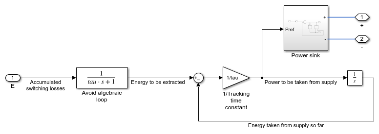
The Probe (IGBT) block accesses the accumulatedSwitchingLosses variable in the logged simulation data that records the IGBT switching losses. The Apply switching losses subsystem, shown below, extracts these losses from the supply. With an ideal (infinite) supply, it is not possible to apply an energy impulse to reduce the supply total energy. Instead, you can use an energy tracking loop to extract the demanded power from the supply. The Half-Bridge (Ideal, Switching) block uses the same method. The time constant tau sets the speed of the tracking.
Plot Simulation Results
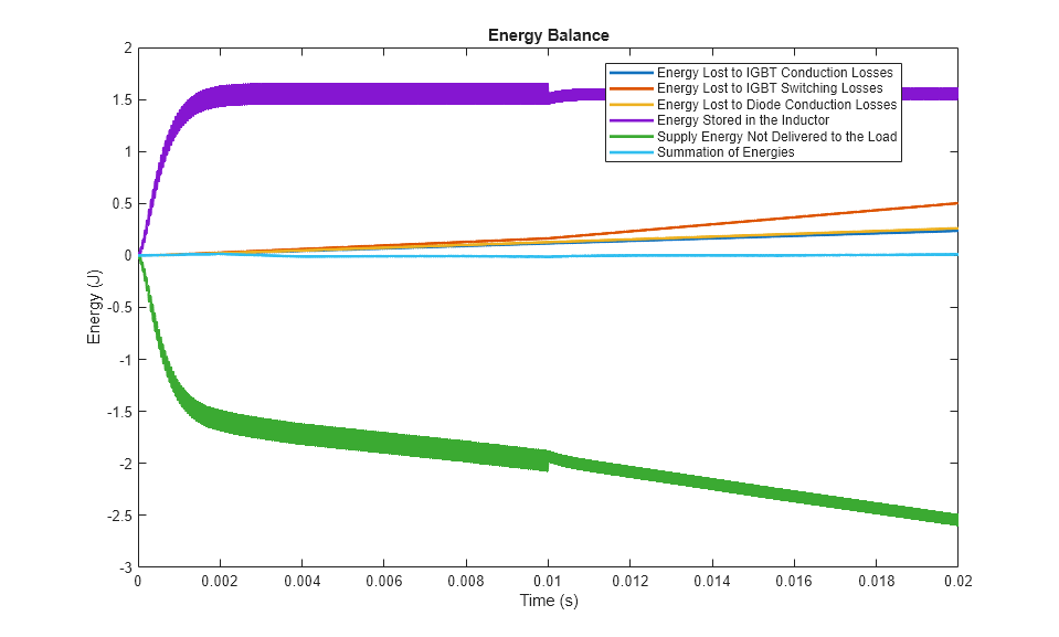
The plot below shows the IGBT energy balance. The sum of the stored energy, supply energy, load energy, and energy losses shows that the total energy is constant, as expected. The small drift is due to numerical integration error and the tracking time constant. This small drift confirms that the IGBT switching losses are drawn correctly from the supply.
Generate Summary of Losses
The ee_getPowerLossSummary function reports the losses incurred by the circuit components from the logged simulation data. The Power column reports conduction losses and the SwitchingLosses column reports the semiconductor switching losses.
ans =

  5×3 table

                           LoggingNode                            Power     SwitchingLosses
    __________________________________________________________    ______    _______________

    {'IGBTSwitchingLossApplicationToSupply.Load'             }    7224.9             0
    {'IGBTSwitchingLossApplicationToSupply.Diode'            }    13.067             0
    {'IGBTSwitchingLossApplicationToSupply.IGBT'             }    11.872        25.123
    {'IGBTSwitchingLossApplicationToSupply.Gate_driver.Rgate'}         0             0
    {'IGBTSwitchingLossApplicationToSupply.Inductor'         }         0             0
See Also
Probe | IGBT (Ideal, Switching) | Half-Bridge (Ideal,
Switching) | ee_getPowerLossSummary