Flyback Converter
This model shows how a flyback converter can step-up a 5V DC source into a 15V DC regulated supply. The voltage is increased by creating a time-varying voltage across a transformer primary. The transformer steps up the voltage which is then rectified back to DC by the diode. Closed-loop control over the output voltage is effected by controlling the switching frequency on the primary side.
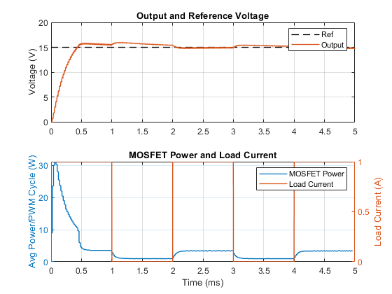
The model can be used to size the transformer inductance and smoothing capacitor values, as well as to design the feedback controller gains and switching frequency. The model includes a detailed representation of the switching device, in this case an enhancement-mode MOSFET, which lets you check that the switching device dissipated power is within acceptable limits. The Power Sensor block is used here in averaging mode, thereby calculating the average power over each PWM cycle. Postprocessing data available in Simscape™ logging can also show the power dissipated by the MOSFET.
Model

Simulation Results from Simscape Logging
The plot below shows the output voltage as compared to the reference voltage. It also shows the changing load current and the dissipated power of MOSFET averaged over the PWM cycle.

See Also
N-Channel MOSFET | Mutual Inductor | Controlled PWM Voltage | Gate Driver