Process and Import Manufacturer Data into MOSFET (Ideal, Switching) Block
This example shows how to process 1D tabular data that you extract from a manufacturer data sheet into the format that the MOSFET (Ideal, Switching) block parameters use. Then, you import the parameter values into the block. This example is step two in a series of examples that take you through parameterizing a MOSFET (Ideal, Switching) block and creating a part collection.
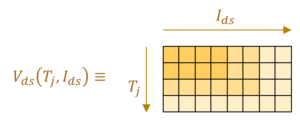
Extracted data often requires processing to make it compatible with the lookup table requirements of the block. Common issues include mismatched axes, non-ascending values, NaN values, and data orientation differences. This illustration shows the expected structure of the 2D lookup table. The drain-source voltage,, is a function of the drain-source current, , and junction temperature, . The voltage varies with current along the x-axis and with temperature along the y-axis.
The create2DMatrix function, which is attached to this example as a supporting file, processes the data you extracted in the previous step so that you can use it to parameterize the MOSFET (Ideal, Switching) block. The function performs these common processing tasks:
Reorient I-V curves into V-I curves — By default, the block expects voltage lookup tables for the MOSFET and integral diode. If the extracted data has voltage values in the first column, then you need to swap the order of the columns so that voltage values are along the y-axis.
Mirror third quadrant data into the first quadrant — The referenced data sheet provides diode curves. This data is in the third quadrant of the I-V curve. The MOSFET (Ideal, Switching) block uses forward conduction data, , for diodes. This data is in the first quadrant of the I-V curve. To satisfy the requirements of the block, mirror the extracted data into the first quadrant before using it for parameterization.
Convert table data to
simscape.Valuetype — Converting data intosimscape.Valueimproves unit handling and provides compatibility with Simscape™ blocks.Remove rows containing NaNs and duplicates —
NaNvalues, duplicate values, or non-ascending entries can cause errors during model compilation.Prune and interpolate data for ascending order — When combining multiple lookup tables, each table can contain data at different x-values. Interpolation aligns all the tables to a common x-axis, so you can combine the tables into a unified 2D matrix.
Discard points outside of first quadrant and insert (0,0) as the first data point — The block physics expects data only in the first quadrant, starting from the origin.
Concatenate vectors to form a 2D matrix — Concatenating vectors combines the cleaned and aligned vectors into the structure required by the block.
For more information about the create2dMatrix function, you can open the function documentation.
doc create2DMatrix
Load the data you extracted from the manufacturer data sheet in the previous step. For this example, you can load ExtractedData. This file is a supporting MAT file that contains the variables you need.
load("ExtractedData.mat");Process Switch Parameter Data
Process the data for the switch parameters using the create2DMatrix function.
[SwitchParams.IV.OnStateVoltageLookupTable, ...
    SwitchParams.IV.OnStateCurrentBreakpoints, ...
    SwitchParams.IV.TemperatureBreakpoints] = create2DMatrix([temp1IV temp2IV],"V","A",IVat25degC,IVat175degC);
Process Switching Loss Parameter Data
The referenced data sheet provides switching loss data at a single temperature point only, so the switch-on loss, and switch-off loss, are vectors instead of matrices. To prune the data and get a common drain-source vector for switching losses, , use the create2DMatrix function.
[lossLookupTable,...
    SwitchParams.Loss.OnStateCurrentBreakpoints, ...
    SwitchParams.Loss.TemperatureBreakpoints] = create2DMatrix([tempLoss,tempLoss],"A","uJ",lossAt400V);

SwitchParams.Loss.SwitchOnLossLookupTable = lossLookupTable(1,:);
SwitchParams.Loss.SwitchOffLossLookupTable = lossLookupTable(2,:);

SwitchParams.Loss.OffStateVoltageBreakpoints = vLoss;
SwitchParams.Loss.TemperatureBreakpoints = SwitchParams.Loss.TemperatureBreakpoints(1);
Read additional switch parameters from data sheet.
SwitchParams.IV.ThresholdVoltage = simscape.Value(2.3,"V"); MOSFETLeakageCurrent = simscape.Value(
0.00005,"A"); ratedVds = simscape.Value(
650,"V"); SwitchParams.IV.OffStateConductance = MOSFETLeakageCurrent/ratedVds; % [S], 'Zero gate voltage drain current' divided by 'max drain-source voltage'
Process Diode Parameter Data
Process the data for the diode parameters using the create2DMatrix function.
[DiodeParams.IV.ForwardVoltageLookupTable,...
    DiodeParams.IV.ForwardCurrentBreakpoints,...
    DiodeParams.IV.TemperatureBreakpoints] = create2DMatrix([temp1DiodeIV temp2DiodeIV],"V","A",diodeIVat25degC,diodeIVat175degC);
Import Parameters to MOSFET (Ideal, Switching) Block
Use the processed switch and diode data to parameterize the MOSFET (Ideal, Switching) block in the MOSFETTestHarness model.
model = "MOSFETTestHarness";
blockPath = strcat(model,"/","MOSFET");
open_system(model);

applyMOSFETParametersToBlock(blockPath,SwitchParams,DiodeParams);
Validate Parameterization
To check that the parameterization is correct, you can generate a derived data sheet. Derived data sheets contain summary tables and characteristic plots like those that device manufacturers provide. You can compare the derived data sheet with the manufacturer data sheet to check for discrepancies. To open the script that generates a derived data sheet, click the Open live script button next to the Derived data sheet parameter in the Utilities section of the MOSFET (Ideal, Switching) block mask. Then, run the script or click the Generate Data Sheet button.