Building Climate Control
This example models a climate control system for a building by using a Stateflow® chart. Building occupants rely on automated systems to maintain a desired climate. Climate conditions require consistent monitoring and adjusting, because temperature and humidity are dynamic. While monitoring the fluctuating conditions, the chart activates different subsystems to adjust and maintain a desired climate in the model.
Examine the Stateflow Chart
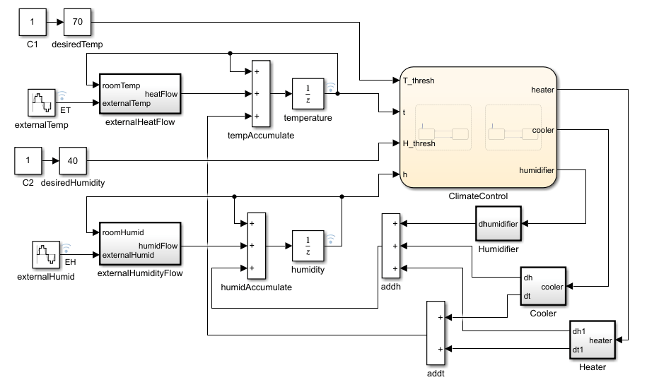
In this example, the Stateflow chart, ClimateControl controls the subsystem outputs. The chart uses four inputs:
T_threshis the target temperature.tis the current building temperature.H_threshis the target humidity.his the current building humidity.
The chart contains two parallel states, Temp and Humidity.
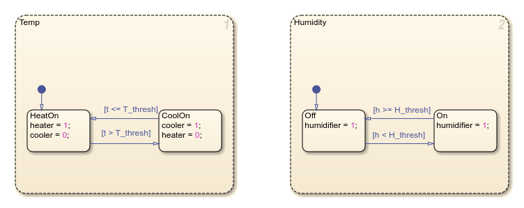
The Temp state controls whether the system is heating or cooling by using two substates, HeatOn and CoolOn. The default active substate is HeatOn. If the temperature of the building is greater than the desired temperature, the chart transitions to CoolOn.
Similarly, in the Humidity state, there are two substates, Off and On. Off is the default active substate, which means that when the chart first becomes active, the humidifier is off. If the humidity of the building is less than the desired humidity, the chart transitions to On.
Examine the Model Subsystems
In the model, the Humidifier, Cooler, and Heater subsystems represent the systems that regulate the climate of the building. The Humidifier subsystem includes a Switch block that engages based on the output of the ClimateControl chart. When the humidity input, h, equals 1, the system outputs a value of 1.5. Otherwise, the system maintains a zero output state.

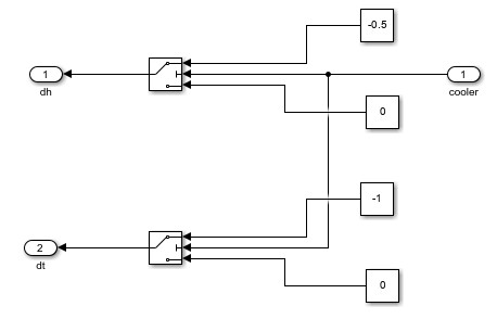
The Heater subsystem activates when the value of the heater data is 1. When HeatOn is active, the Heater subsystem outputs a value of 1 through the dt1 port and affects humidity with a -0.5 output through dh1.
The Cooler subsystem is similar to the Heater subsystem, but produces inverse temperature effects. When CoolOn is active, the Cooler subsystem outputs a value of -1 at the dt port and a value of -0.5 at the dh port, which affects the humidity of the system.
Due to the ClimateControl chart, the Cooler and Heater subsystems do not activate at the same time.
Examine the External Subsystems
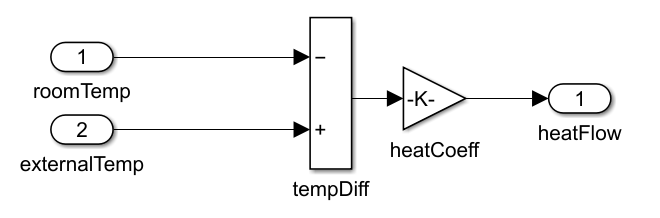
The external heat flow calculations depend on the temperature differential between the interior and exterior environments. The externalHeatFlow system applies a coefficient multiplier that represents the effectiveness of the insulation, where higher coefficients indicate lower insulation values.
The externalHumidityFlow subsystem uses similar calculations to the externalHeatFlow subsystem. The subsystem processes the humidity differential using a coefficient that models the moisture transfer between interior and exterior spaces.
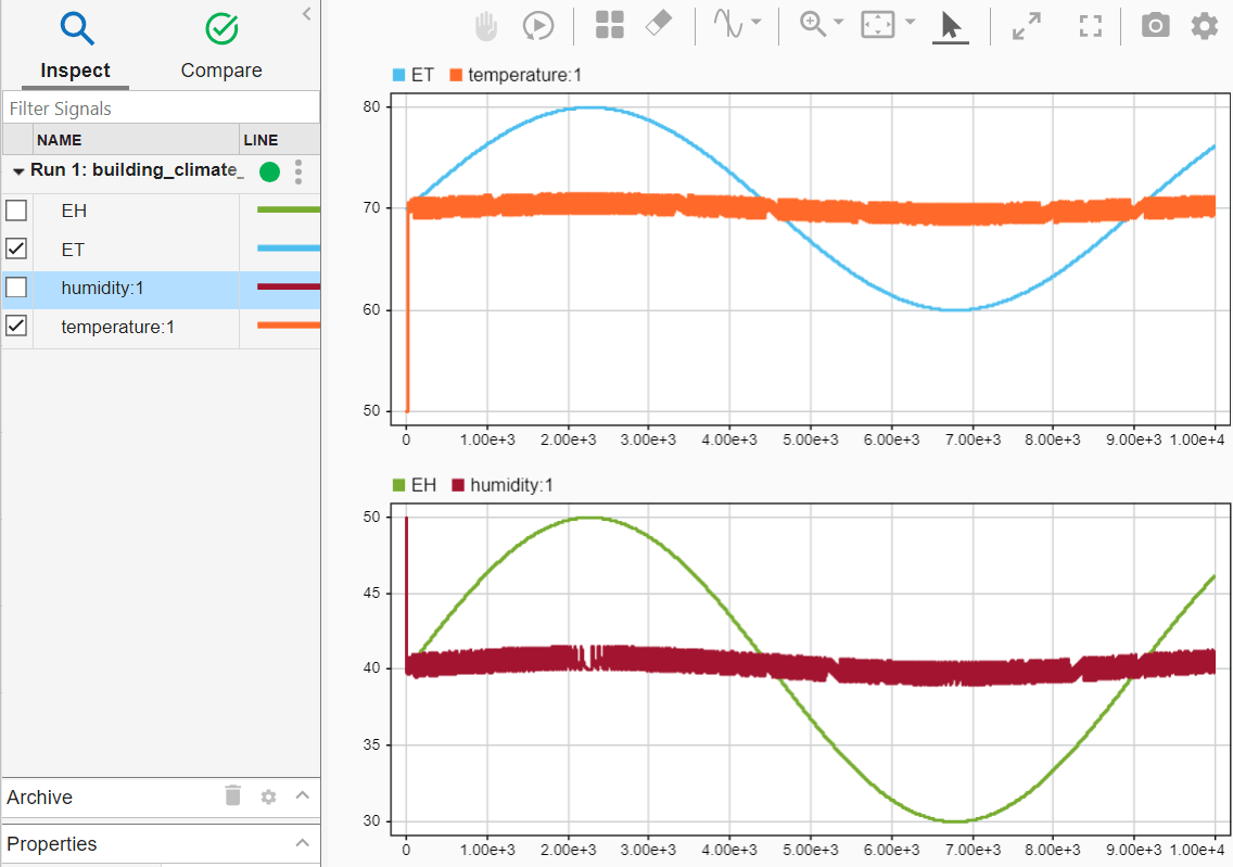
Simulate the Model
To view the model data in the Simulink Data Inspector, click Run. You can monitor the relationship between external temperature and building temperature in the top plot. The bottom plot tracks external humidity versus the building humidity.
Explore and Modify the Model
You can modify the environmental response of the model by adjusting the external temperature signal amplitude or changing the external humidity signal parameters. The performance characteristics of the system can be fine-tuned by modifying heater output values, adjusting cooler system parameters, or revising insulation coefficients to match specific building conditions.