show3D
R2026bVisualize UAV scenario in 3-D
Syntax
Description
[
visualizes latest states of the platforms and sensors in the UAV scenario
ax,plottedFrames] = show3D(scene)scene along with all static meshes. The function also returns the
axes on which the scene is plotted and the frames on which each object is plotted.
[
visualizes the UAV scenario at the specified ax,plottedFrames] = show3D(scene,time)time.
[
specifies additional options using name-value arguments.ax,plottedFrames] = show3D(___,Name=Value)
Examples
Create a UAV scenario, and specify the update rate, stop time, and reference location. The reference location sets the geodetic origin of the scenario in latitude, longitude, and altitude.
scene = uavScenario(UpdateRate=200,StopTime=2,ReferenceLocation=[46, 42, 0]);
Add a custom inertial frame named MAP to the scenario. The MAP frame is offset 1 meter east from the default ENU (east-north-up) frame. Custom inertial frames enable you to define local coordinate systems for specific regions or tasks within the scenario.
addInertialFrame(scene,"ENU","MAP",trvec2tform([1 0 0]));
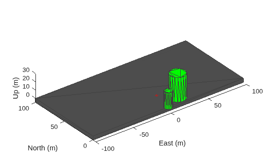
Add one ground mesh and two cylindrical obstacle meshes to the scenario. The polygon mesh represents the ground surface. The first cylinder is specified using Cartesian coordinates relative to the scenario origin. The second cylinder uses geographic coordinates (latitude, longitude, and radius) by setting UseLatLon to true, which is useful when you want to place obstacles at known geodetic positions.
addMesh(scene,"Polygon",{[-100 0; 100 0; 100 100; -100 100],[-5 0]},[0.3 0.3 0.3]);
addMesh(scene,"Cylinder",{[20 10 10],[0 30]},[0 1 0]);
addMesh(scene,"Cylinder",{[46 42 5],[0 20]},[0 1 0],UseLatLon=true);
Add a UAV platform with a specified waypoint trajectory to the scenario. The trajectory defines a flight path through three waypoints with arrival times at 0, 1, and 2 seconds.
traj = waypointTrajectory(Waypoints=[0 -20 -5; 20 -20 -5; 20 0 -5],TimeOfArrival=[0 1 2]);
uavPlat = uavPlatform("UAV",scene,Trajectory=traj);
Add meshes to the UAV platform for visualization. The first mesh is a quadrotor body with a wingspan of 4 meters displayed in red. Then, add a geofence boundary to constrain the UAV flight region.
updateMesh(uavPlat,"quadrotor",{4},[1 0 0],eul2tform([0 0 pi]));
addGeoFence(uavPlat,"Polygon",{[-50 0;50 0;50 50;-50 50],[0 100]},true,ReferenceFrame="ENU");
Attach an inertial navigation system (INS) sensor to the UAV platform. The INS sensor provides position, velocity, and orientation measurements during simulation.
insModel = insSensor;
ins = uavSensor("INS",uavPlat,insModel,MountingLocation=[4 0 0]);
Visualize the scenario in 3D.
ax = show3D(scene);
axis(ax,"equal");
Set up and start the scenario.
% Set up scenario
setup(scene);

% Start scenario
while advance(scene)
    % Update sensor readings
    updateSensors(scene);

    % Visualize the scenario
    show3D(scene,"Parent",ax,"FastUpdate",true);
    drawnow limitrate
end
Input Arguments
Name-Value Arguments
Output Arguments
Version History
Introduced in R2020b

